是德科技 | KEYSIGHT
XA5系列N9032B 信号分析仪,2Hz至8.4/13.6/26.5/44/50/55GHz 详细指标
台式信号与频谱分析仪
Frequency option Frequency range DC coupled 508 2 Hz to 8.4 GHz 513 2 Hz to 13.6 GHz 526
2 Hz to 26.5 GHz
Minimal frequency DC coupled AC coupled (option 508
513 and 526)
PA off, LNA off 2 Hz
10 MHz
Swept spectrum analysis (these bands are not applicable to wide-bandwidth IQ analysis)
Swept frequency band LO multiple (N) Frequency range 0 1 2 Hz to 3.6 GHz 1 1 3.5 to 8.4 GHz 2 2
8.3 to 13.6 GHz
Accuracy (total) ± [ (Initial accuracy) + (aging rate x time since last adjustment) + (temperature stability)]
Aging rate ± 3 x
10–8 / year
Temperature stability ± 4.5 x
10–9 over full temperature range
Achievable initial calibration accuracy ± 3.1 x
10–8
Example frequency reference accuracy
1 year after last adjustment
= ± (3 ×10⁻⁸ + 4.5 ×10⁻⁹ + 3.1 x
10–8)
条件:Center frequency = 1 GHz, 10 Hz RBW, 10 Hz VBW ≤ (0.25 Hz x N) p–p in 20 ms nominal (N = LO multiple, see band table above)
Frequency readout accuracy (start, stop, center, marker) ± (marker frequency x frequency reference accuracy + 0.10 % x span + 5 % x RBW + 2 Hz +
0.5 x horizontal resolution) where horizontal resolution is span/(sweep points-1)
Accuracy ± (marker frequency x frequency reference accuracy +
0.100 Hz)
Delta counter accuracy ± (delta frequency x frequency reference accuracy +
0.141 Hz)
Counter resolution
0.001 Hz
Range 0 Hz (zero span)
10 Hz to maximum frequency of instrument
Swept ± (0.1 % x span + horizontal resolution) where horizontal resolution is span/(sweep points
–1)
FFT ± (0.1 % x span + horizontal resolution) where horizontal resolution is span/(sweep points
–1)
Range Span = 0 Hz
1 μs to 6000 s
Span ≥ 10 Hz
1 ms to 4000 s
条件:Span ≥ 10 Hz, swept ± 0.01% nominal
Span ≥ 10 Hz, FFT ± 40% nominal
Span = 0 Hz
± 0.01% nominal
Span = 0 Hz or FFT
–150 to +500 ms
Span ≥ 10 Hz, swept
0 to 500 ms
Gate methods Gated LO; Gated video; Gated FFT
Gate length range (except method = FFT)
1 μs to 5.0 s
Gate delay range
0 to 100.0 s
Gate delay jitter
33.3 ns p-p (nom)
Resolution bandwidth (RBW) filters (see also IQ Analysis section)
Range (with –3 dB bandwidth, standard) 1 Hz to 3 MHz (10% steps), 4, 5, 6
8, and 10 MHz
条件:RBW range Accuracy 1 Hz to 100 kHz ± 0.5% (± 0.022 dB) 110 kHz to 1.0 MHz (< 3.6 GHz CF) ± 1.0% (± 0.044 dB) 1.1 to 2 MHz (< 3.6 GHz CF) ± 0.07 dB (nominal)
2.2 to 3 MHz (< 3.6 GHz CF) 0 to –0.2 dB (nominal)
4 to 10 MHz (< 3.6 GHz CF) 0 to –0.4 dB (nominal)
RBW range Accuracy 1 Hz to 1.3 MHz ± 2% (nominal) 1.5 MHz to 3 MHz
• (≤ 3.6 GHz center frequency) ± 7% (nominal)
• (> 3.6 GHz center frequency) ± 8% (nominal)
• (≤ 3.6 GHz center frequency) ± 15% (nominal)
• (> 3.6 GHz center frequency) ± 20% (nominal)
Selectivity (–60 dB/–3 dB) 4.1: 1 (nominal)
Bandwidth accuracy (-3 dB)
4 MHz to 10 MHz
EMI bandwidths (CISPR 16-1-1; requires N90EMEMCB or N6141EM0E) 200 Hz, 9 kHz, 120 kHz
1 MHz
EMI bandwidths (MIL-STD-461; requires N90EMEMCB or N6141EM0E) 10 Hz, 100 Hz, 1 kHz, 10 kHz, 100 kHz
1 MHz
The preselector can have a significant passband ripple. To avoid ambiguous results, the
-4dB bandwidth is characterized
Center frequency Mean bandwidth (-
4 dB)
Option 508, 513 and 526 Option 544 and 550 Option
555
5 GHz 58 MHz 46 MHz
39 MHz
10 GHz 57 MHz 52 MHz
46 MHz
15 GHz 59 MHz 53 MHz
47 MHz
20 GHz 64 MHz 55 MHz
48 MHz
25 GHz 74 MHz 56 MHz
52 MHz
35 GHz
N/A 62 MHz 57 MHz 44 GHz 70 MHz 64 MHz 50 GHz 76 MHz
72 MHz
Range 1 Hz to 3 MHz (10% steps), 4, 5,6, 8 MHz, and wide open (labeled
50 MHz)
Normal, peak, sample, negative peak, log power average, RMS average, and voltage average
With N90EMEMCB or N6141EM0E Add quasi-peak and EMI average to above
条件:External 1 Y Y Y Jitter up to ~33 ns p-p (nominal) External 2 Y Y Y
External 3 Y Jitter < 20 ps (nominal)
RF Burst Y Y IF Path ≤
40 MHz only
Video (IF Mag) Y Y In 255 MHz IF Path only; at greater bandwidths, ADC trigger is similar
ADC Y Similar to Video, but operates digitally on mag[I,Q], prior to decimation,
filtering, and corrections. Available for bandwidth >
255 MHz.
Periodic Y Y Y Repetitive “frame” trigger, at precise interval, following an External or RF
Video (independent of Display Scaling and Reference Level) Specifications Supplemental information
Minimum settable level
-170 dBm Useful range limited by noise
Highest allowed mixer level (the highest allowed mixer level depends on
the IF Gain. It is nominally
–10 dBm for Preamp Off and IF Gain = Low)
+ 2 dB (nominal)
Detector = Normal, Peak, Sample or Negative Peak Triggers on the signal before detection, which is similar to the displayed
Detector = Average Triggers on the signal before detection, but with a single-pole filter added
to give similar smoothing to that of the average detector
Sweep Type = FFT Triggers on the signal envelope in a bandwidth wider than the FFT width
Level range
−40 to −10 dBm plus attenuation
Noise will limit trigger level range at high frequencies, such as above
15 GHz
条件:With positive slope trigger. Trigger level with negative slope is nominally 1 to 4 dB lower than positive slope.
Absolute
± 2 dB + Absolute Amplitude
条件:Most cases (including RF Burst Level Type = Relative) > 80 MHz (nominal)
Bandwidth (-10 dB)
If the start or center frequency is too close to zero, LO feedthrough can
degrade or prevent triggering. How close is too close depends on the
条件:made with preselector on (in circuit). These settings impact amplitude accuracy and range.
Amplitude characteristics vary by user-selectable front-end path. Swept SA measurements are normally
Default selection following power-on, boot-up, or PRESET. Settings provide best dynamic range and
lowest internally-generated distortion. Suitable for harmonics, IMD, spurious in presence of large
signals, etc. unless noise-limited.
1b Preselector, LNA on
Requires P08, P13, P26, P44, P4L, P50, P5L, P55, or P5N. Settings provide lower DANL, compared to
1a, while preserving very good dynamic range. Suitable for distortion measurements (harmonics, IMD,
etc.) when a lower noise floor is needed. 1c Preselector, PA on Requires P08, P13, P26, P44, P4L, P50, P5L, P55, or P5N. Settings provide lower DANL, compared to 1b.
1d Preselector, LNA on
条件:wider RBW setting to achieve equivalent noise floors, so can make spur searching faster.
Requires P08, P13, P26, P44, P4L, P50, P5L, P55, or P5N. Settings provide lowest possible DANL,
compared to 1c. Best for finding low-level spurs, oscillations, etc. near the noise floor. Allows use of
2a
条件:lower DANL at higher frequencies, when compared with 1a. Path not active below 3.6 GHz.
Preselector, LNP Bypasses the preamplifier. Settings provide the lowest distortion and best dynamic range, yet with
2b Preselector, LNP,
Bypasses the preamplifier. Requires P08, P13, P26, P44, P4L, P50, P5L, P55, or P5N. Settings
provide the lower DANL, compared to 2a, while preserving very good dynamic range. Path not active at
3a
条件:attenuation), including below 3.6 GHz. Good for wideband digitizer and FFT measurements.
best EVM at low input power for below 3.6 GHz. Good for wideband digitizer and FFT measurements.
narrowband swept measurements only. Not generally recommended for digital demodulation.
Bypasses preselector. Settings provide very good EVM floor at mid-high input power region (using
Recommend using path 4a if above
3.6 GHz.
3b LNA on
Bypasses preselector. Requires P08, P13, P26, P44, P4L, P50, P5L, P55, or P5N. Settings provide
Otherwise use path 4b if above
3.6 GHz.
3c PA on
Bypasses preselector. Requires P08, P13, P26, P44, P4L, P50, P5L, P55, or P5N. Good for wideband
digitizer and FFT measurements. Settings allowed only for very low power levels since preselector is
bypassed. Not generally recommended for digital demodulation.
3d LNA on, PA on Bypasses preselector. Requires P08, P13, P26, P44, P4L, P50, P5L, P55, or P5N. Good sensitivity for
4a
条件:region (using attenuation) for above 3.6 GHz. Best for wideband digitizer and FFT measurements.
P5N. Settings provide best EVM floor for low input power region (using attenuation) for above 3.6 GHz.
Best for wideband digitizer and FFT measurements. Otherwise use path 3b if below 3.6 GHz.
Bypasses both preamplifier and preselector. Settings provide best EVM floor for mid-high input power
Otherwise use path 3a if below
3.6 GHz.
4b LNP, MPB, LNA on
Bypasses both preamplifier and preselector. Requires P08, P13, P26, P44, P4L, P50, P5L, P55, or
Displayed average noise level (DANL) to +30 dBm (for preamp Off)
DANL to +24 dBm (for frequency opts ≤
526 with preamp On)
DANL to +20 dBm (for frequency opts >
526 with preamp On)
Input mechanical attenuator range (2 Hz to 55 GHz)
0 to 70 dB in 2 dB steps
Electronic attenuator (option EA3)
Frequency range
2 Hz to 3.6 GHz
Electronic attenuator range 0 to 24 dB
1 dB steps
Full attenuation range (mechanical + electronic) 0 to 94 dB
1 dB steps
最大安全输入电平 (最大 applied 至 RF 输入连接器)
Average total power (with and without preamp)
+30 dBm (1 W)
Peak pulse power (< 10 μs pulse width, < 1% duty cycle, and input attenuation ≥ 30 dB)
+50 dBm (100 W)
AC coupled (Option 508, 513 or 526)
± 100 Vdc
Log scale
0.1 to 1 dB/division in 0.1 dB steps
1 to 20 dB/division in 1 dB steps (10 display divisions)
Scale units dBm, dBmV, dBμV, dBmA, dBμA, V, W, A
条件:Frequency Response 1a. Standard path frequency response (swept, preselector on, LNA off, PA off) 10 dB input attenuation, relative to reference conditions (50 MHz), preselector centering applied above 3.6 GHz
Frequency Full range 20 to 30° C Typical, unless otherwise stated
0 dB input attenuation, relative to reference conditions (50 MHz), preselector centering applied above 3.6 GHz
Frequency Full range 20 to 30° C Typical, unless otherwise stated
0 dB input attenuation, relative to reference conditions (50 MHz), preselector centering applied above 3.6 GHz
Frequency Full range 20 to 30° C Typical, unless otherwise stated
0 dB input attenuation, relative to reference conditions (50 MHz), preselector centering applied above 3.6 GHz
Frequency Frequency response (nominal)
0 dB input attenuation, relative to reference conditions (50 MHz), preselector centering applied above 3.6 GHz
Frequency Full range 20 to 30 °C Typical, unless otherwise stated
10 dB input attenuation, relative to reference conditions (50 MHz), preselector centering applied above 3.6 GHz
Frequency Full range 20 to 3 0°C Typical, unless otherwise stated
Frequency Full range 20 to 30 °C Typical, unless otherwise stated
Maximum error relative to reference conditions (50 MHz). Mechanical attenuation set to default/calibrated setting of 10 dB.
attenuation) (nominal) 3c. Std, PA on (0 dB input attenuation) (nominal) 3d. Std, LNA on, PA on
(0 dB input attenuation) (nominal)
Frequency 4a. FBP (10 dB input attenuation) (nominal) 4b. FBP, LNA on (0 dB input attenuation) (nominal)
Attenuation Full range Typical 12 to 40 dB ± 0.14 dB ± 0.04 dB 2 to 8 dB, or > 40 dB ± 0.18 dB ± 0.06 dB 0 dB ± 0.05 dB (nominal)
Attenuation > 2 dB at other frequencies (nominal)
all settings auto-coupled except Auto Swp Time = Accy, any Reference Level, any vertical Scale.
Path Full range 20 to 30 °C Typical AutoAlign = Light, nominal
For absolute amplitude accuracy at any frequency in the 1a. Std Path, use the following formulas:
Note1: Absolute amplitude accuracy is the total of all amplitude measurement errors, and applies over the following subset of settings and conditions:
• Span < 5 MHz (nominal additional error for span ≥ 5 MHz is is 0.02 dB)
2 Hz to 30 MHz ± 0.50 dB ± 0.40 dB
± 0.15 dB
> 30 MHz to 50 MHz ± 0.40 dB ± 0.35 dB
± 0.20 dB
> 50 MHz to 3.6 GHz ± 0.60 dB ± 0.35 dB
± 0.20 dB
> 3.6 to 5.2 GHz ± 3.50 dB ± 1.70 dB
± 1.00 dB
> 5.2 to 8.4 GHz ± 2.50 dB ± 1.50 dB
± 0.60 dB
> 8.4 to 13.6 GHz ± 2.00 dB ± 1.50 dB
± 0.60 dB
> 13.6 to 17.1 GHz ± 2.20 dB ± 1.50 dB
± 0.60 dB
> 17.1 to 22.0 GHz ± 2.30 dB ± 1.50 dB
± 0.60 dB
> 22.0 to 26.5 GHz ± 2.50 dB ± 2.00 dB
± 0.70 dB
> 26.5 to 34.5 GHz ± 3.50 dB ± 2.30 dB
± 1.00 dB
> 34.5 to 36.5 GHz ± 5.20 dB ± 2.50 dB
± 1.50 dB
> 36.5 to 55.0 GHz ± 5.20 dB ± 3.10 dB
± 1.50 dB
1b. Standard path, LNA on frequency response (swept, preselector on, LNA on, PA off)
30 MHz to 3.6 GHz ± 0.70 dB ± 0.50 dB
± 0.20 dB
> 3.6 to 5.2 GHz ± 3.50 dB ± 1.90 dB
± 1.10 dB
> 5.2 to 8.4 GHz ± 2.70 dB ± 1.70 dB
± 0.70 dB
> 8.4 to 13.6 GHz ± 2.30 dB ± 1.70 dB
± 0.70 dB
> 13.6 to 17.1 GHz ± 2.60 dB ± 1.70 dB
± 0.70 dB
> 17.1 to 22.0 GHz ± 2.80 dB ± 1.90 dB
± 0.70 dB
> 22.0 to 26.5 GHz ± 3.00 dB ± 2.30 dB
± 0.80 dB
> 26.5 to 34.5 GHz ± 3.70 dB ± 2.60 dB
± 1.20 dB
> 34.5 to 55.0 GHz ± 5.30 dB ± 3.20 dB
± 1.60 dB
1c. Standard path, PA on frequency response (swept, preselector on, LNA off, PA on)
9 kHz to 100 kHz
± 0.40 dB (nom)
> 100 kHz to 50 MHz ± 0.80 dB ± 0.68 dB
± 0.35 dB
> 50 MHz to 3.6 GHz ± 0.80 dB ± 0.60 dB
± 0.20 dB
> 3.6 to 5.2 GHz ± 3.50 dB ± 2.30 dB
± 1.20 dB
> 5.2 to 8.4 GHz ± 2.70 dB ± 2.00 dB
± 0.80 dB
> 8.4 to 13.6 GHz ± 2.50 dB ± 2.00 dB
± 0.80 dB
> 13.6 to 17.1 GHz ± 2.50 dB ± 2.00 dB
± 0.95 dB
> 17.1 to 22.0 GHz ± 2.90 dB ± 2.20 dB
± 0.95 dB
> 22.0 to 26.5 GHz ± 3.70 dB ± 2.70 dB
± 1.20 dB
> 26.5 to 34.5 GHz ± 4.50 dB ± 2.90 dB
± 1.30 dB
> 34.5 to 55.0 GHz ± 5.20 dB ± 3.40 dB
± 1.60 dB
2b. Low-noise path (LNP) frequency response (low-noise path enabled, preselector on, LNA on, PA off)
< 3.6 GHz If tuning to <3.6 GHz, then actually using Standard Path with LNA ON
> 8.4 to 17.1 GHz
± 0.70 dB
> 17.1 to 26.5 GHz
± 1.00 dB
> 26.5 to 34.5 GHz
± 1.00 dB
> 34.5 to 55.0 GHz
± 1.40 dB
1d. Standard path, LNA on, PA on frequency response (swept, preselector on, LNA on, PA on)
< 3.6 GHz (if tuning <
3.6 GHz, then standard path with LNA on is used)
3.6 to 5.2 GHz ± 3.50 dB ± 2.10 dB
± 1.30 dB
> 5.2 to 8.4 GHz ± 2.80 dB ± 1.80 dB
± 0.75 dB
> 8.4 to 13.6 GHz ± 2.40 dB ± 1.80 dB
± 0.75 dB
> 13.6 to 17.1 GHz ± 2.40 dB ± 1.80 dB
± 0.75 dB
> 17.1 to 22.0 GHz ± 2.70 dB ± 2.10 dB
± 0.75 dB
> 22.0 to 26.5 GHz ± 3.20 dB ± 2.50 dB
± 0.90 dB
> 26.5 to 34.5 GHz ± 3.90 dB ± 2.80 dB
± 1.30 dB
> 34.5 to 36.5 GHz ± 5.30 dB ± 3.40 dB
± 1.70 dB
> 36.5 to 45.0 GHz ± 5.30 dB ± 3.40 dB
± 1.70 dB
> 45.0 to 50.0 GHz ± 5.80 dB ± 3.40 dB
± 1.70 dB
> 50.0 to 55.0 GHz ± 6.20 dB ± 3.40 dB
± 1.70 dB
2a. Low-noise path (LNP) frequency response (low-noise path enabled, preselector on, LNA off, PA off)
< 3.6 GHz If tuning to <
3.6 GHz, then actually using Standard Path
3.6 to 5.2 GHz ± 3.50 dB ± 1.80 dB
± 1.00 dB
> 5.2 to 8.4 GHz ± 2.50 dB ± 1.50 dB
± 0.75 dB
> 8.4 to 13.6 GHz ± 2.00 dB ± 1.50 dB
± 0.75 dB
> 13.6 to 17.1 GHz ± 2.00 dB ± 1.50 dB
± 0.75 dB
> 17.1 to 22.0 GHz ± 2.50 dB ± 2.00 dB
± 0.90 dB
> 22.0 to 26.5 GHz ± 3.00 dB ± 2.50 dB
± 1.05 dB
> 26.5 to 34.5 GHz ± 3.60 dB ± 2.80 dB
± 1.10 dB
> 34.5 to 36.5 GHz ± 5.30 dB ± 3.10 dB
± 1.40 dB
> 36.5 to 45.0 GHz ± 4.40 dB ± 3.10 dB
± 1.40 dB
> 45.0 to 55.0 GHz ± 5.30 dB ± 3.10 dB
± 1.40 dB
3a. Microwave preselector bypass (MPB) path frequency response (MBP enabled, LNA off, PA off)
10 dB input attenuation, relative to reference
conditions (50 MHz)
3.6 to 8.4 GHz ± 1.40 dB ± 1.00 dB
± 0.50 dB
> 8.4 to 13.6 GHz ± 1.60 dB ± 1.10 dB
± 0.55 dB
> 13.6 to 17.1 GHz ± 1.80 dB ± 1.10 dB
± 0.55 dB
> 17.1 to 22.0 GHz ± 2.00 dB ± 1.40 dB
± 0.60 dB
> 22.0 to 26.5 GHz ± 2.20 dB ± 1.60 dB
± 0.70 dB
> 26.5 to 34.5 GHz ± 2.90 dB ± 1.80 dB
± 0.90 dB
> 34.5 to 36.5 GHz ± 5.50 dB ± 3.00 dB
± 1.50 dB
> 36.5 to 45.0 GHz ± 4.00 dB ± 3.00 dB
± 1.50 dB
> 45.0 to 55.0 GHz ± 5.50 dB ± 3.00 dB
± 1.50 dB
Electronic attenuator (option EA3) frequency response
Frequency Full range
20 to 30 °C Typical, unless stated otherwise
2 Hz to 9 kHz ± 0.80 dB ± 0.60 dB
± 0.25 dB
9 kHz to 50 MHz ± 0.80 dB ± 0.60 dB
± 0.25 dB
50 MHz to 3.6 GHz ± 0.60 dB ± 0.40 dB
± 0.20 dB
Note: Signal frequencies above
18 GHz are prone to additional response errors due to modes in the Type -N connector used. Only
analyzers with frequency Option 526 that do not also have input connector Option C35 will have these modes. With the use
of Type- N to APC 3.5 mm adapter part number 1250- 1744, there are nominally six such modes. The effect of these modes
with this connector are included within these specifications.
3b, 3c, 3d. Microwave preselector bypass (MPB) path frequency response (MBP path enabled, relative to 10 dB, excludes
0 dB setting)
Frequency
3b. MPB, LNA on (0 dB input
3.6 GHz to 8.4 GHz ± 0.40 dB ± 0.30 dB
± 0.40 dB
> 8.4 to 13.6 GHz ± 0.50 dB ± 0.40 dB
± 0.50dB
> 13.6 to 17.1 GHz ± 0.50 dB ± 0.40 dB
± 0.50 dB
> 17.1 to 26.5 GHz ± 0.50 dB ± 0.50 dB
± 0.60 dB
> 26.5 to 34.5 GHz ± 0.60 dB ± 0.60 dB
± 0.70 dB
> 34.5 to 55 GHz ± 1.10 dB ± 1.20 dB
± 1.10 dB
4a
4b. Full bypass (FBP) path frequency response (full bypass path enabled)
3.6 to 8.4 GHz ± 0.40 dB
± 0.40 dB
> 8.4 to 13.6 GHz ± 0.40 dB
± 0.50 dB
> 13.6 to 17.1 GHz ± 0.40 dB
± 0.50 dB
> 17.1 to 26.5 GHz ± 0.40 dB
± 0.50 dB
> 26.5 to 34.5 GHz ± 0.50 dB
± 0.60 dB
> 34.5 to 55 GHz ± 1.00 dB
± 1.00 dB
Attenuator switching uncertainty (50 MHz reference frequency, relative to 10 dB reference setting, LNA off, PA off)
1a. Standard path (swept, preselector on, LNA off, PA off)
> 3.6 to 8.4 GHz
± 0.5 dB
> 8.4 to 26.5 GHz
± 0.7 dB
> 26.5 to 55 GHz
± 1.0 dB
Total absolute amplitude accuracy (at
50 MHz)
At 50 MHz, 10 dB attenuation, RBW < = 1 MHz, input signal -10 to -50 dBm, for Path 1a or -40 to -70 dBm for Path
1b and 1c
1a. Std ± 0.35 dB ± 0.30 dB ± 0.10 dB
± 0.17 dB
1b. Std (LNA on, preamp off) ± 0.40 dB ± 0.35 dB ± 0.15 dB
± 0.19 dB
1c. Std (LNA off, preamp on) ± 0.40 dB ± 0.35 dB ± 0.15 dB
± 0.17 dB
With electronic attenuator (at 50MHz, 0 to 24 dB attenuation, RBW < = 1 MHz, input signal -7 to -25 dBm, all settings auto-coupled except Auto Swp Time = Accy, any Reference Level, any vertical Scale) 1a. Std ± 0.35 dB ± 0.30 dB ± 0.10 dB
± 0.17 dB
At any frequency ± (Abs Amp at 50 MHz + Frequency Response)
Wide range of signal levels, resolution bandwidths, reference levels, attenuation
• Input signal
−10 to −50 dBm (details below)
• 全部设置 auto-耦合 except Swp 时间 Rules = 精度
条件:This absolute amplitude accuracy specification includes the sum of the following individual specifications under the conditions listed above: Scale Fidelity,
performance at all levels with acceptable test times and yields. So the performance is not warranted at lower levels, but we fully expect it to be the same.
• The wide range of conditions of RBW, signal level, VBW, reference level and display scale are described above.
• There are 44 quasi-random combinations used, tested at a 50 MHz signal frequency.
• We compute the 95th percentile proportion with 95% confidence for this set observed over a statistically significant number of instruments.
frequencies that are chosen to not correspond with the frequency response adjustment frequencies.
• We again compute the 95th percentile proportion with 95% confidence for this set observed over a statistically significant number of instruments.
• We also compute the 95th percentile accuracy of tracing the calibration of the 50 MHz absolute amplitude accuracy to a national standards organization.
• To that RSS we add the environmental effects of temperature variations across the 20 to 30°C range.
• These computations and measurements are made with the mechanical attenuator only in circuit, set to the reference state of 10 dB.
inclusive, with the mechanical attenuator set to 10 dB. The 95th percentile result was 0.20 dB.
Standard path, 10 dB input attenuation, 50 MHz (reference condition) 1.09:1 (nominal)
Standard path, 0 dB input attenuation, 0.01 to 3.6 GHz 2.05:1 (nominal)
• Combinations of low signal level and wide RBW use VBW ≤
30 kHz to reduce noise
• When using FFT sweeps, the signal must be at the center frequency.
Reference Level Accuracy, Display Scale Switching Uncertainty, Resolution Bandwidth Switching Uncertainty
50 MHz Amplitude Reference Accuracy, and the
accuracy with which the instrument aligns its internal gains to the
50 MHz Amplitude Reference. The only difference between signals within the range above
–50 dBm and those signals below that level is the scale fidelity. Our specifications and experience show no difference between signals above and below this
level. The only reason our Absolute Amplitude Uncertainty specification does not go below this level is that noise detracts from our ability to verify the
Note 2: Absolute amplitude accuracy for a wide range of signal and measurement settings, covers the
95th percentile proportion with 95% confidence. Here are
the details of what is covered and how the computation is made:
• Also, the frequency response relative to the
50 MHz response is characterized by varying the signal across a large number of quasi-random verification
• We also compute the
95th percentile accuracy of tracing the calibration of the relative frequency response to a national standards organization
• We take the root-sum-square of these four independent Gaussian parameters
• A similar process is used for computing the result when using the electronic attenuator under a wide range of settings: all even settings from 4 through
24 dB
VSWR (voltage standing wave ratio) at RF Input (95th percentile)
条件:and between FBP and non-FBP operation, but the details, such as the frequencies of the peaks and valleys, will shift.
inclusive, with the mechanical attenuator set to 10 dB. The 95th percentile result was 0.20 dB.
Option 1a Std, LNA off, PA off (10 dB attenuation)
1b Std, LNA on, PA off
1d Std, LNA on, PA on
(0 dB attenuation)
1c Std, LNA off, PA on
(0 dB attenuation) 508
513
and 526
544 and
10 MHz to 3.6 GHz x x 1.20 1.30
1.70
3.6 to 8.4 GHz x x 1.30 1.50
1.60
8.4 to 13.6 GHz x 1.50 1.60
1.60
13.6 to 17.1 GHz x 1.60 1.70
1.70
17.1 to 26.5 GHz
26.5 to 34.5 GHz x 1.50 1.60
1.60
34.5 to 50 GHz x 1.70 1.70
1.80
50.0 to 55.0 GHz x 1.70 1.70
1.70
The magnitude of the mismatch over the range of frequencies will be very similar between MPB and non-MPB operation, between LNP and non-LNP operation,
A similar process is used for computing the result when using the electronic attenuator under a wide range of settings: all even settings from 4 through
24 dB
Figure 1. VSWR vs. frequency (0 to 3.5 GHz), 1a. Standard Path, 10 dB attenuation, measured on
3 units
Figure 2. VSWR vs. frequency (3.5 to 26.5 GHz), 1a. Standard Path, 10 dB attenuation, measured on
3 units
Figure 3. VSWR vs. frequency (26.5 to 50 GHz and 50 to 55 GHz), 1a. Standard Path
10 dB attenuation, measured
Resolution bandwidth switching uncertainty (reference to 30 kHz RWB)
20 to 30 °C
1 Hz to 1.5 MHz RBW <
± 0.03 dB
1.6 MHz to 2.7 MHz RBW <
± 0.05 dB
4, 5, 6, 8, 10 MHz RBW
± 0.30 dB
Log scale
–170 to +30 dBm in 0.01 dB steps
Linear scale
707 pV to 7.07 V with 0.11% (0.01 dB) resolution
Accuracy (Only affects the display, not the measurement, so it causes no additional error in
measurement results from trace data or markers.)
0 dB
条件:Display scale fidelity (Log-linear fidelity, relative to the reference condition -25 dBm input through 10 dB attenuation, thus -35 dBm at the input mixer)
Switching between linear and log (Only affects the display, not the measurement, so it causes no
additional error in measurement results from trace data or markers.)
0 dB
Log scale/div switching (Only affects the display, not the measurement, so it causes no additional
error in measurement results from trace data or markers.)
0 dB
-18 dBm ≤ ML ≤ -10 dBm ± 0.10 dB total
± 0.04 dB
ML < -18 dBm input mixer level ± 0.07 dB
± 0.02 dB
Preamplifiers (2 stages: Low-Noise Amplifier LNA, Pre-Amplifier PA)
Low-Noise Amplifier (LNA) Pre-Amplifier (PA)
条件:Noise figure 4 to 8 dB (nominal) 10 dB (nominal)
Gain (up to 50 GHz) 20 dB (nominal) 30 dB (nominal)
When LNA and PA are used simultaneously, gain = 40 dB (nominal)
Gain (50 to 55 GHz) 13 dB (nominal) 16 dB (nominal)
When LNA and PA are used simultaneously, gain = 24 dB (nominal)
Option P08 20 MHz to 8.4 GHz
9 kHz to 8.4 GHz
Option P13 20 MHz to 13.6 GHz
9 kHz to 13.6 GHz
Option P26 20 MHz to 26.5 GHz
9 kHz to 26.5 GHz
Option P44, P4L 20 MHz to 44 GHz
9 kHz to 44 GHz
Option P50, P5L 20 MHz to 50 GHz
9 kHz to 50 GHz
Option P55, P5N 20 MHz to 55 GHz
9 kHz to 55 GHz
For options P4L/P5L/P5N: ≥
43.5 GHz both LNA and PA cannot be used simultaneously
1 dB gain compression
条件:interfering signal must be in order to cause a 1 dB change in an on-screen signal.
the measurement results can change with RL changes when the input attenuation is set to auto.
• Mixer power level (dBm) = total power at the input (dBm) − input attenuation (dB).
• Total power at the preamp (dBm) = total power at the input (dBm) − input attenuation (dB).
• Large signals, even at frequencies not shown on the screen, can cause the analyzer to mismeasure
on-screen signals because of two-tone gain compression. This specification tells how large an
• Specified at 1 kHz RBW with 100 kHz tone spacing. The compression point will nominally equal the
specification for tone spacing greater than
5 times the prefilter bandwidth. At smaller spacings, ADC
clipping may occur at a level lower than the
1 dB compression point.
• Reference level and off-screen performance: The reference level (RL) behavior differs from some
earlier analyzers in a way that makes this analyzer more flexible. In other analyzers, the RL
controlled how the measurement was performed as well as how it was displayed. Because the
logarithmic amplifier in these analyzers had both range and resolution limitations, this behavior was
necessary for optimum measurement accuracy. The logarithmic amplifier in this signal analyzer,
however, is implemented digitally such that the range and resolution greatly exceed other instrument
limitations. Because of this, the analyzer can make measurements largely independent of the setting
of the RL without compromising accuracy. Because the RL becomes a display function, not a
measurement function, a marker can read out results that are off-screen, either above or below,
without any change in accuracy. The only exception to the independence of RL and the way in which
the measurement is performed is in the input attenuation setting: When the input attenuation is set to
auto, the rules for the determination of the input attenuation include dependence on the reference
level. Because the input attenuation setting controls the tradeoff between large signal behaviors
(third-order intermodulation, compression, and display scale fidelity) and small signal effects (noise),
• The low noise path, when in use, does not substantially change the compression- to-noise dynamic
range or the TOI-to-noise dynamic range because it mostly just reduces losses in the signal path in
front of all significant noise, TOI and compression-affecting circuits. In other words, the compression
threshold and the third-order intercept both decrease and to the same extent as that to which the
Standard path
1 dB gain compression (swept, standard, preselector on)
Large signals, even at frequencies not shown on the screen, can cause the analyzer to mismeasure on-screen signals because of two-tone gain
compression. This specification tells how large an interfering signal must be in order to cause a
1 dB change in an on-screen signal. Mixer power level (dBm)
条件:Gain compression (nominal) 1a. PA Off 1b. LNA 1c. PA 20 to 40 MHz +3 dBm –16 dBm –13 dBm
> 40 MHz to 3.6 GHz +6 dBm –16 dBm
–13 dBm
> 3.6 to 13.5 GHz +5 dBm –16 dBm
–27 dBm
> 13.5 to 26.5 GHz +1 dBm –20 dBm
–30 dBm
> 26.5 to 50 GHz 0 dBm –16 dBm
–32 dBm
条件:This table applies without Option FS1 or FS2, fast sweep. With Option FS1 or FS2, which is a standard option in the UXA, this table applies for sweep rates
rates, available with FS1 or FS2. Sweep rate is defined to be span divided by sweep time. If the sweep rate is ≤ 1.1 times RBW-squared, the table applies.
time is 1 ms, then the effective RBW computes to 100 kHz. This would result in an IF Prefilter Bandwidth from the third row, nominally 303 kHz.
Zero span or swept, RBW= Sweep Type = FFT, FFT width = –3 dB bandwidth (nominal)
that are manually chosen to be the same as or slower than "traditional" sweep rates, instead of the much faster sweep rates, such as auto coupled sweep
Otherwise, compute an "effective RBW" = Span / (SweepTime × RBW). To determine the IF Prefilter Bandwidth, look up this effective RBW in the table instead
of the actual RBW. For example, for RBW = 3 kHz, Span = 300 kHz, and Sweep time = 42 ms, we compute that Sweep Rate =
7.1 MHz/s, while RBW-squared
is 9 MHz/s. So the Sweep Rate is < 1.1 times RBW-squared and the table applies; row 1 shows the IF Prefilter Bandwidth is nominally
8.9 kHz. If the sweep
≤ 3.9 kHz < 4.01 kHz
8.9 kHz
4.3 to 27 kHz < 28.81 kHz
79 kHz
30 to 160 kHz < 167.4 kHz
303 kHz
180 to 390 kHz < 411.9 kHz
966 kHz
430 kHz to 10 MHz < 7.99 MHz
10.9 MHz
条件:Noise Floor Extension (Option NF2) improves DANL by 8 to 12 dB, for standard path.
Input terminated, Sample or Average detector, Averaging type set to Log, IF Gain = High
1 Hz Resolution
Bandwidth
0 dB input attenuation.
1a. Standard path (swept, preselector on, LNA off, PA off)
条件:Full range 20 to 30 °C Typical, unless otherwise
stated 508, 513 and 526 544 and 550
555
2 to 10 Hz x
条件:> 10 to 100 Hz x –127 dBm (nominal)
> 100 Hz to 1 kHz x –129 dBm (nominal)
> 1 to 9 kHz x –138 dBm (nominal)
–125 dBm (nominal)
> 9 to 100 kHz x x x –141 dBm –141 dBm
–146 dBm
> 100 kHz to 1 MHz x x x –148 dBm –150 dBm
–153 dBm
> 1 to 10 MHz x x x –152 dBm –153 dBm
–156 dBm
> 10 MHz to 1.2 GHz x x x –151 dBm –152 dBm
–155 dBm
> 1.2 to 2.1 GHz x x x –148 dBm –150 dBm
–152 dBm
> 2.1 to 3.6 GHz x x x –147 dBm –148 dBm
–150 dBm
> 3.6 to 6.6 GHz
x –148 dBm –150 dBm
–152 dBm
x –148 dBm –149 dBm
–151 dBm
x –145 dBm –146 dBm
–148 dBm
> 6.6 to 8.4 GHz x x –148 dBm –150 dBm
–152 dBm
x –147 dBm –148 dBm
–150 dBm
> 8.4 to 13.6 GHz x x –146 dBm –147 dBm
–151 dBm
x –146 dBm –147 dBm
–149 dBm
> 13.6 to 17 GHz x x x –146 dBm –147 dBm
–151 dBm
> 17 to 22.5 GHz x x x –144 dBm –146 dBm
–149 dBm
> 22.5 to 26.5 GHz x x x –140 dBm –142 dBm
–146 dBm
> 26.5 to 30 GHz x –139 dBm –141 dBm
–145 dBm
x –139 dBm –141 dBm
–143 dBm
> 30 to 34 GHz x x –135 dBm –138 dBm
–143 dBm
> 34 to 37 GHz x x –131 dBm –133 dBm
–139 dBm
> 37 to 40 GHz x x –131 dBm –133 dBm
–138 dBm
> 40 to 45 GHz x x –127 dBm –130 dBm
–136 dBm
> 45 to 50 GHz x x –122 dBm –126 dBm
–133 dBm
> 50 to 53 GHz x –122 dBm –126 dBm
–131 dBm
> 53 to 55 GHz x –120 dBm –121 dBm
–127 dBm
1b. Standard path, LNA on (swept, preselector on, LNA on, PA off)
Noise Floor Extension (Option NF2) improves DANL by
9 to 11 dB, for standard path, LNA on
条件:Full range 20 to 30 °C Typical, unless otherwise
stated 508, 513 and 526 544 and 550
555
< 20 MHz x x x
Not permitted with LNA on
条件:> 20 to 40 MHz x –164 dBm (nominal)
Noise Floor Extension (Option NF2) improves DANL by 5 to 12 dB, for standard path, PA on.
> 40 to 500 MHz x –165 dBm –165 dBm
–167 dBm
x x –162 dBm –163 dBm
–165 dBm
> 500 MHz to 2.5 GHz x –165 dBm –165 dBm
–167 dBm
x x –164 dBm –165 dBm
–166 dBm
> 2.5 GHz to 3.6 GHz x x x –161 dBm –163 dBm
–166 dBm
> 3.6 to 4.7 GHz
x –163 dBm –164 dBm
–167 dBm
x –162 dBm –163 dBm
–165 dBm
x –161 dBm –162 dBm
–164 dBm
> 4.7 to 8.4 GHz
x –162 dBm –164 dBm
–166 dBm
x –161 dBm –163 dBm
–165 dBm
x –160 dBm –162 dBm
–164 dBm
> 8.4 to 13.5 GHz x x x –161 dBm –163 dBm
–165 dBm
> 13.5 to 17.1 GHz x x x –161 dBm –163 dBm
–164 dBm
> 17.1 to 22.5 GHz x –159 dBm –161 dBm
–163 dBm
x x –158 dBm –161 dBm
–162 dBm
> 22.5 to 26.5 GHz x x x –155 dBm –156 dBm
–159 dBm
> 26.5 to 27 GHz x x –153 dBm –155 dBm
–160 dBm
> 27 to 34.5 GHz x x –148 dBm –152 dBm
–156 dBm
> 34.5 to 42.5 GHz x x –142 dBm –146 dBm
–152 dBm
> 42.5 to 47 GHz x x –138 dBm –141 dBm
–148 dBm
> 47 to 50 GHz x x –134 dBm –138 dBm
–145 dBm
> 50 to 53 GHz x –134 dBm –138 dBm
–143 dBm
> 53 to 55 GHz x –131 dBm –132 dBm
–138 dBm
1c. Standard path, PA on (swept, preselector on, LNA off, PA on)
条件:Full range 20 to 30 °C Typical, unless otherwise
stated 508, 513 and 526 544 and 550
555
> 100 kHz to 200 kHz x x x
条件:> 200 kHz to 500 kHz x x x –162 dBm (nominal)
> 500 kHz to 1 MHz x –156 dBm (nominal)
Noise Floor Extension (Option NF2) improves DANL by 5 to 11 dB, for standard path, LNA on, PA on.
–151 dBm (nominal)
1 MHz to 2.1 GHz x x x –163 dBm –163 dBm
–165 dBm
> 2.1 to 3.6 GHz x x x –160 dBm –161 dBm
–163 dBm
> 3.6 to 8.4 GHz x x x –161 dBm –162 dBm
–164 dBm
> 8.4 to 13.6 GHz x x x –161 dBm –162 dBm
–164 dBm
> 13.6 to 17.1 GHz x x x –160 dBm –162 dBm
–164 dBm
> 17.1 to 20.0 GHz x x x –159 dBm –160 dBm
–163 dBm
> 20.0 to 26.5 GHz x x x –155 dBm –156 dBm
–160 dBm
> 26.5 to 30 GHz x X –155 dBm –158 dBm
–160 dBm
> 30 to 34 GHz x X –153 dBm –157 dBm
–159 dBm
> 34 to 40 GHz x X –150 dBm –154 dBm
–156 dBm
> 40 to 45 GHz x X –147 dBm –150 dBm
–152 dBm
> 45 to 50 GHz x x –144 dBm –147 dBm
–151 dBm
> 50 to 53 GHz X –144 dBm –146 dBm
–149 dBm
> 53 to 55 GHz x –139 dBm –141 dBm
–146 dBm
1d. Standard path, LNA on, PA on (swept, preselector on, LNA on, PA on)
条件:Full range 20 to 30 °C Typical, unless otherwise
> 20 to 40 MHz x N/A –164 dBm (nominal)
(for Option P44, P50, and P55) x x –151 dBm –153 dBm –157 dBm
(for Option P50 and P55) x x –150 dBm –152 dBm –156 dBm
(for Option P55) x –149 dBm –150 dBm –154 dBm
(for Option P55) x –144 dBm –146 dBm –151 dBm
(for Option P4L, P5L and P5N) x x –138 dBm –141 dBm –148 dBm
(for Option P5L and P5N) x x –134 dBm –138 dBm –145 dBm
(for Option P5N) x –134 dBm –138 dBm –143 dBm
(for Option P5N) x –131 dBm –132 dBm –138 dBm
Noise Floor Extension (Option NF2) improves DANL by 8 to 12 dB, for low-noise path.
stated 508, 513 and 526 544 and 550
555
< 20 MHz x x x Not permitted with LNA on
> 40 to 500 MHz x –165 dBm –165 dBm
–167 dBm
x x –162 dBm –163 dBm
–165 dBm
> 500 MHz to 2.5 GHz x –165 dBm –165 dBm
–167 dBm
x x –164 dBm –165 dBm
–166 dBm
> 2.5 to 3.6 GHz x x x –161 dBm –163 dBm
–165 dBm
> 3.6 to 8.4 GHz x –164 dBm –165 dBm
–167 dBm
x x –162 dBm –164 dBm
–167 dBm
> 8.4 to 13.5 GHz x x x –163 dBm –164 dBm
–167 dBm
> 13.5 to 17.1 GHz x x x –161 dBm –163 dBm
–166 dBm
> 17.1 to 23 GHz x x x –161 dBm –163 dBm
–165 dBm
> 23 to 26.5 GHz x x x –158 dBm –160 dBm
–163 dBm
> 26.5 to 36.5 GHz x x –156 dBm –159 dBm
–161 dBm
> 36.5 to 43.5 GHz x x –152 dBm –155 dBm
–158 dBm
> 43.5 to 47 GHz
> 47 to 50 GHz
> 50 to 53 GHz
> 53 to 55 GHz
> 43.5 to 47 GHz
> 47 to 50 GHz
> 50 to 53 GHz
> 53 to 55 GHz
2a. Low-Noise Path (low-noise path enabled, preselector on, LNA off, PA off)
条件:Full range 20 to 30 °C Typical, unless otherwise
Frequency 2b. LNP path, LNA on (nominal)
Frequency 3a. MPB path (nominal) 3b. MPB, LNA on (nominal)
If using microwave preselector path (MPB) use path 3b for digital demodulation.
Frequency Full range 20 to 30 °C Typical, unless otherwise stated
4b. Full bypass (FBP) path DANL (low-noise path enabled, preselector bypass on, LNA on) (nominal)
stated 508, 513 and 526 544 and 550
555
< 3.6 GHz x x x Not permitted with low noise path
3.6 to 8.4 GHz
x –151 dBm –153 dBm
–155 dBm
x –150 dBm –152 dBm
–154 dBm
x –149 dBm –150 dBm
–153 dBm
8.4 to 17.1 GHz x –151 dBm –153 dBm
–155 dBm
x x –150 dBm –152 dBm
–154 dBm
17.1 to 23 GHz x x x –149 dBm –151 dBm
–153 dBm
23 to 26.5 GHz x x x –148 dBm –150 dBm
–152 dBm
26.5 to 29 GHz x x –146 dBm –148 dBm
–151 dBm
29 to 34.5 GHz x x –141 dBm –143 dBm
–146 dBm
34.5 to 50 GHz x x –137 dBm –139 dBm
–144 dBm
50 to 53 GHz x –137 dBm –139 dBm
–143 dBm
53 to 55 GHz x –134 dBm –135 dBm
–140 dBm
2b. Low-noise path DANL (low-noise path enabled, preselector on, LNA on, PA off)
< 3.6 GHz Not permitted with low noise path
> 17.1 to 23 GHz
–164 dBm
> 23 to 26.5 GHz
–162 dBm
> 26.5 to 29 GHz
–162 dBm
> 29 to 34.5 GHz
–160 dBm
> 34.5 to 50 GHz
–154 dBm
> 50 to 53 GHz
–152 dBm
> 53 to 55 GHz
–151 dBm
3a
3b. Microwave preselector bypass (MPB) path DANL (MPB path enabled)
3.6 to 8.4 GHz -154 dBm
-163 dBm
> 8.4 to 17.1 GHz -151 dBm
-162 dBm
> 17.1 to 22.5 GHz -150 dBm
-161 dBm
> 22.5 to 26.5 GHz -146 dBm
-159 dBm
> 26.5 to 30 GHz -145 dBm
-159 dBm
> 30 to 34 GHz -142 dBm
-158 dBm
> 34 to 40 GHz -137 dBm
-154 dBm
> 40 to 45 GHz -134 dBm
-153 dBm
> 45 to 50 GHz -130 dBm
-150 dBm
> 50 to 53 GHz -130 dBm
-150 dBm
> 53 to 55 GHz -130 dBm
-146 dBm
4a. Full bypass (FBP) path DANL (low-noise path enabled, preselector bypass on, LNA off, PA off)
3.6 to 8.4 GHz -154 dBm -156 dBm
-158 dBm
> 8.4 to 13.6 GHz -154 dBm -155 dBm
-158 dBm
> 13.6 to 17.1 GHz -154 dBm -155 dBm
-158 dBm
> 17.1 to 22 GHz -152 dBm -153 dBm
-157 dBm
> 22 to 26.5 GHz -152 dBm -153 dBm
-156 dBm
> 26.5 to 29 GHz -151 dBm -152 dBm
-157 dBm
> 29 to 34.5 GHz -150 dBm -152 dBm
-155 dBm
> 34.5 to 45 GHz -147 dBm -149 dBm
-152 dBm
> 45 to 50 GHz -145 dBm -147 dBm
-151 dBm
> 50 to 53 GHz -145 dBm -147 dBm
-150 dBm
> 53 to 55 GHz -143 dBm -144 dBm
-148 dBm
> 8.4 to 13.6 GHz
-163 dBm
> 13.6 to 17.1 GHz
-162 dBm
> 17.1 to 22 GHz
-161 dBm
> 22 to 26.5 GHz
-160 dBm
> 26.5 to 29 GHz
-160 dBm
> 29 to 34.5 GHz
-159 dBm
> 34.5 to 45 GHz
-154 dBm
> 45 to 50 GHz
-153 dBm
> 50 to 53 GHz
-153 dBm
> 53 to 55 GHz
-152 dBm
Residuals, Images, and Spurious Responses
条件:Zero span or FFT or other frequencies –100 dBm (nominal)
Residual responses (input terminated
0 dB attenuation)
200 kHz to 8.4 GHz (swept)
–100 dBm
Image responses (标配通路, LNA 关, PA 关)
条件:26.5 to 55 GHz f+45 MHz -90 dBc (nominal)
42 to 55 GHz f+645 MHz -75 dBc (nominal)
Mixer level Tuned frequency (f) Excitation frequency Full range Typical
-10 dBm
10 MHz to 26.5 GHz f+45 MHz –80 dBc
–105 dBc
10 MHz to 3.6 GHz f+10,245 MHz –80 dBc
–106 dBc
10 MHz to 3.6 GHz f+645 MHz –80 dBc
–101 dBc
> 3.6 to 13.6 GHz f+645 MHz –78 dBc
–87 dBc
> 13.6 to 17.1 GHz f+645 MHz –74 dBc
–84 dBc
> 17.1 to 22 GHz f+645 MHz –70 dBc
–82 dBc
> 22 to 26.5 GHz f+645 MHz –68 dBc
–75 dBc
-30 dBm
26.5 to 34.5 GHz f+645 MHz -70 dBc
-94 dBc
34.4 to 42 GHz f+645 MHz -59 dBc
-76 dBc
Other spurious responses (input-related, standard path, LNA off, PA off)
N is the LO multiplication factor. Refer to earlier table for the N value versus frequency ranges. Performance is nominally the same, with PA on, and in low-noise
First RF order (f ≥
10 MHz from carrier)
Carrier frequency ≤ 26.5 GHz -10 dBm -80 dBc +
20*log(N) including IF feedthrough, LO harmonic
条件:Carrier frequency > 26.5 GHz -30 dBm -90 dBc (nominal)
Carrier frequency > 26.5 GHz -30 dBm -90 dBc (nominal)
45 Hz ≤ f < 200 MHz from carrier -73 dBc + 20*log(N) (nominal)
Nominally –40 dBc under large magnetic (0.38 Gauss rms) or vibrational (0.21 g rms) environmental stimuli.
Frequency of the Fundamental Preamp level Distortion (nominal) SHI (nominal)
Frequency of the Fundamental Preamp level Distortion (nominal) SHI (nominal)
Frequency of the fundamental Preamp level Distortion (nominal) SHI (nominal)
Frequency Full range 20 to 30 °C Typical, unless otherwise stated
Frequency TOI (nominal) 30 to 200 MHz 0 dBm
Frequency TOI (nominal) 10 to 200 MHz +2 dBm
Frequency TOI (nominal) 3.6 to 4 GHz –22 dBm
Higher RF order (f ≥
10 MHz from carrier)
Carrier frequency ≤ 26.5 GHz -40 dBm -80 dBc +
20*log(N) including higher order mixer responses
LO-related spurious responses 200 Hz ≤ f < 10 MHz from carrier -10 dBm -68 dBc +
20*log(N)
-72 dBc +
20*log(N) (typical)
Second-Harmonic Intercept (SHI)
1a. Standard path (swept, preselector on, LNA off, PA off)
Frequency of the fundamental Mixer level Distortion SHI 10 to 500 MHz –15 dBm –65 dBc
+50 dBm
> 500 MHz to 1.8 GHz –15 dBm –60 dBc
+45 dBm
> 1.8 to 3 GHz –15 dBm –77 dBc
+62 dBm
> 3 to 4.5 GHz –15 dBm –76 dBc
+61 dBm
> 4.5 to 6.5 GHz –15 dBm –77 dBc
+62 dBm
> 6.5 to 10 GHz –15 dBm –80 dBc
+65 dBm
> 10 to 13.25 GHz –15 dBm –80 dBc
+65 dBm
> 13.25 to 25 GHz –15 dBm –68 dBc
+53 dBm
1b. Standard path (swept, preselector on, LNA on, PA off) Preamp level = Input level – Input attenuation
15 to 40 MHz –45 dBm –65 dBc
+20 dBm
> 40 MHz to 1 GHz –45 dBm –63 dBc
+18 dBm
> 1 to 1.8 GHz –45 dBm –61 dBc
+16 dBm
> 1.8 to 13.25 GHz –45 dBm –63 dBc
+18 dBm
1c. Standard path (swept, preselector on, LNA off, PA on) Preamp level = Input level – Input attenuation
10 to 400 MHz –45 dBm –78 dBc
+33 dBm
> 400 MHz to 1.8 GHz –45 dBm –73 dBc
+28 dBm
> 1.8 to 4 GHz –50 dBm –55 dBc
+5 dB
> 4 to 13.25 GHz –50 dBm –60 dBc
+10 dBm
> 13.25 to 25 GHz –50 dBm –50 dBc
0 dBm
1d. Standard path (swept, preselector on, LNA on, PA on) Preamp level = Input level – Input attenuation
1.8 to 4 GHz –50 dBm –44 dB
–6 dBm
> 4 to 13.25 GHz –50 dBm –47 dBc
–3 dBm
2a. Low-noise path: SHI (swept, Low-noise path enable, preselector on, LNA off, PA off)
Frequency of the fundamental Mixer level Distortion SHI 1.8 to 2.5 GHz –15 dBm –95 dBc
+80 dBm
> 2.5 to 10 GHz –15 dBm –101 dBc
+86 dBm
> 10 to 13.25 GHz –15 dBm –101 dBc
+86 dBm
> 13.25 to 25 GHz –15 dBm –92 dBc
+77 dBm
Third-Order Intercept (TOI)
1a. Standard path (swept, preselector on, LNA off, PA off)
Two –16 dBm (10 MHz to 26.5 GHz) or –20 dBm (26.5 GHz to 50 GHz) tones at input mixer with tone separation ≥
100 kHz
10 to 200 MHz +9 dBm +12 dBm
+18 dBm
> 200 to 600 MHz +16 dBm +17 dBm
+20 dBm
> 600 MHz to 2.0 GHz +18.5 dBm +19.5 dBm
+22 dBm
> 2.0 to 3.6 GHz +18.5 dBm +19.5 dBm
+23 dBm
> 3.6 to 7.1 GHz +15 dBm +16 dBm
+18 dBm
> 7.1 to 10 GHz +14.5 dBm +15 dBm
+18 dBm
> 10 to 13.6 GHz +17.5 dBm +18.5 dBm
+22 dBm
> 13.6 to 19 GHz +7 dBm +9.5 dBm
+12 dBm
> 19 to 23 GHz +12 dBm +14 dBm
+16 dBm
> 23 to 26.5 GHz +13 dBm +14.5 dBm
+18 dBm
> 26.5 GHz to 34.5 GHz +11 dBm +13 dBm +
17 dBm
> 34.5 to 50 GHz + 7 dBm +9 dBm
+14 dBm
1b. Standard path (swept, preselector on, LNA on, PA off)
Two –34 dBm tones at preamp level with tone separation ≥
100 kHz
> 200 to 600 MHz
+1 dBm
> 600 MHz to 3 GHz
+2.5 dBm
> 13.6 to 19 GHz
–5 dBm
1c. Standard path (swept, preselector on, LNA off, PA on)
Two –34 dBm (10 MHz to 3.6 GHz) or –50 dBm (3.6 GHz to 26.5 GHz) tones at LNA input with tone separation ≥
100 kHz
> 200 to 400 MHz
+3 dBm
> 400 MHz to 1 GHz
+4 dBm
> 13.6 to 19 GHz
–17 dB
> 19 to 26.5 GHz
–12 dBm
1d. Standard path (swept, preselector on, LNA on, PA on)
Two –50 dBm tones at preamp level with tone separation ≥
100 kHz
> 8 to 13.6 GHz
–16 dBm
> 13.6 to 19 GHz
–24 dBm
> 19 to 26.5 GHz
–21 dBm
2a. Low-noise path (swept, Low-noise path enable, preselector on, LNA off, PA off)
Two –16 dBm (3.6 GHz to 26.5 GHz) or –20 dBm (26.5 GHz to 50 GHz) tones at input mixer with tone separation ≥
100 kHz
Frequency Full range
20 °C to 30 °C Typical
3.6 to 7.6 GHz +9 dBm +10 dBm
+13 dBm
> 7.6 to 10 GHz +10 dBm +11 dBm
+14 dBm
> 10 to 13.6 GHz +11 dBm +12 dBm
+15 dBm
> 13.6 to 19 GHz +2 dBm +4 dBm
+7 dBm
> 19 to 23 GHz +6 dBm +7 dBm
+10 dBm
> 23 to 26.5 GHz +6 dBm +8 dBm
+10 dBm
> 26.5 GHz to 34.5 GHz +3 dBm +6 dBm
+8 dBm
> 34.5 to 50 GHz +1.5 dBm +4 dBm
+7 dBm
条件:Phase noise Offset Full range 20 to 30 °C Typical, unless otherwise stated
10 Hz Narrow Ref Loop BW –88 dBc/Hz (nominal)
Figure 4. Nominal PXA phase noise at various center frequencies. RBW curves added to show impact of analyzer
phase noise in resolving two closely spaced signals for various RBW filter choices.
Noise sidebands (CF = 1 GHz)
10 Hz Wide Ref Loop BW
The factory test line limit is consistent with a warranted specification of –90 dBc/Hz
–93 dBc/Hz
100 Hz –107 dBc/Hz –107 dBc/Hz
–112 dBc/Hz
1 kHz –124 dBc/Hz −125 dBc/Hz
–129 dBc/Hz
10 kHz –132 dBc/Hz –134 dBc/Hz
–136 dBc/Hz
100 kHz –138 dBc/Hz –139 dBc/Hz
–141 dBc/Hz
1 MHz –144 dBc/Hz –145 dBc/Hz
–146 dBc/Hz
10 MHz –154 dBc/Hz –154 dBc/Hz
–157 dBc/Hz
条件:Bypass) (except < 3.6 GHz), unless otherwise noted. IF Paths at 10, 25, 40, and 255 MHz are enabled by
e.g. instruments with R20 also have R15 and R10 licenses, plus B2X, B40, and B25 paths.
apply under the following settings unless otherwise specified: preselector bypassed, PA off, LNA off, IF
In practice, low end of tuning range limited to < (½*BW), by image folding and LO feedthrough.
All specifications based on preselector by-passed (RF Path either Microwave Preselector Bypass or Full
any of R10, R15, or R20. Each bandwidth option includes and enables all others with lesser bandwidth,
10 MHz Analysis Bandwidth (Standard)
Specifications on this bandwidth apply with center frequencies of 10 MHz and higher. All specifications
gain = Auto, IF gain offset =
0 dB.
10 MHz analysis bandwidth (standard)
Analysis bandwidth range
10 Hz to 10 MHz
Tuning range
2 Hz to 55 GHz
Over-range tuning to 55.5 GHz allowed, but without
corrections, performance not specified
IF frequency 5122.5 MHz (1st IF, center frequency ≤ 3.6 GHz)
322.5 MHz (Final IF)
ADC sample rate
100 MSa/sec
Final data format I & Q pairs, 32 bits each
64 bits/Sa
IQ Analyzer
32,000,001 sample pairs
Length (IQ sample pairs) 536.8 MSa (229 Sa) with 32-bit data packing
268.4 MSa (228 Sa) with 64-bit data packing
Maximum capture time (time record length) 35.8 sec at full
10 MHz BW with 32-bit data
条件:Amplitude RMS (nominal) 0.02 to 3.6 GHz ≤ 10 NA ± 0.20 dB ± 0.12 dB ± 0.10 0.02 dB
Error (95%)
Slope (dB/MHz) (95%)
> 3.6 to 26.5 GHz ≤ 10 Off ± 0.25 dB ± 0.12 dB ± 0.10
0.02 dB
> 26.5 to 34.4 GHz ≤ 10 Off ± 0.30 dB ± 0.12 dB ± 0.10
0.024 dB
> 34.4 to 55 GHz ≤ 10 Off ± 0.35 dB ± 0.12 dB ± 0.10
0.024 dB
条件:Center frequency Span (MHz) Preselector RMS (nominal)
apply under the following settings unless otherwise specified: preselector bypassed, PA off, LNA off,
In practice, low end of tuning range limited to < (½*BW), by image folding and LO feedthrough.
≥ 0.02 GHz, ≤ 3.6 GHz ≤ 10 MHz N/A
0.04°
> 3.6 to 50 GHz ≤ 10 MHz Off
0.07°
> 50 to 55 GHz ≤ 10 MHz Off
0.50°
25 MHz Analysis Bandwidth (Option B25)
Specifications on this bandwidth apply with center frequencies of 15 MHz and higher. All specifications
IFgain = Auto, IF gain offset =
0 dB.
25 MHz analysis bandwidth (Option B25)
Analysis bandwidth range
10 Hz to 25 MHz
Tuning range
2 Hz to 55 GHz
Over-range tuning to 55.5 GHz
allowed, but without corrections, performance not specified
IF frequency 5122.5 MHz (1st IF, center frequency ≤ 3.6 GHz)
322.5 MHz (Final IF)
ADC sample rate
100 MSa/sec
Final data format I & Q pairs, 32 bits each
64 bits/Sa
IQ Analyzer
32,000,001 sample pairs
Length (IQ sample pairs) 536.8 MSa (229 Sa) with 32-bit data packing
268.4 MSa (228 Sa) with 64-bit data packing
Maximum capture time (time record length) 11.9 sec at full
25 MHz BW with 32-bit data packing Capture time increases linearly with decrease in bandwidth
条件:Center frequency Span (MHz) Preselector Amplitude mx error Amplitude RMS (nominal)
0.02 to 3.6 GHz 10 to <= 25 NA ± 0.30 dB
0.05 dB
> 3.6 to 26.5 GHz 10 to <= 25 Off ± 0.40 dB
0.04 dB
> 26.5 to 55 GHz 10 to <= 25 Off ± 0.60 dB
0.04 dB
条件:Center frequency Span (MHz) Preselector RMS (nominal)
Full scale (ADC clipping); preselector bypassed, LNA off, PA off (nominal)
Full scale (ADC clipping level) is a rough estimate of the signal level at which ADC overload occurs. Actual clipping levels vary significantly; this is only a guide.
≥ 0.02 GHz, ≤ 3.6 GHz ≤ 25 MHz N/A
0.12
> 3.6 to 50 GHz ≤ 25 MHz Off
0.28
> 50 to 55 GHz ≤ 25 MHz Off
1.00
Mixer 电平 RF 输入电平 less 衰减设置
条件:Effect of signal frequency ≠ CF Up to ± 1 dB nominal
apply under the following settings unless otherwise specified: preselector bypassed, PA off, LNA off, IF
Center frequency Option Mixer level for IF gain = low Mixer level for IF gain = high
508, 513 and 526 544 and 550
555
2 Hz to 26.5 GHz x x x –8 dBm
–18 dBm
> 26.5 to 50 GHz x x –8 dBm
–18 dBm
> 50 to 55 GHz x –13 dBm
–16 dBm
40 MHz Analysis Bandwidth (Option B40)
Specifications on this bandwidth apply with center frequencies of 65 MHz and higher. All specifications
gain = Auto, IF gain offset =
0 dB.
40 MHz analysis bandwidth Option B40)
Analysis bandwidth range
10 Hz to 40 MHz
Tuning range
2 Hz to 55 GHz
In practice, low end of tuning range limited to < (½*BW), by image
folding and LO feedthrough
Over-range tuning to 55.5 GHz allowed, but without corrections,
performance not specified
IF frequency 5050 MHz (1st IF, center frequency ≤ 3.6 GHz)
250 MHz (Final IF)
ADC sample rate
200 MSa/sec
Final data format I & Q pairs, 32 bits each
64 bits/Sa
IQ Analyzer
32,000,001 sample pairs
Length (IQ sample pairs) 536,870,912 (229 Sa) with 32-bit data packing
268,435,456 (228 Sa) with 64-bit data packing
Maximum capture time (time record length) 8.95 sec at full 40 MHz BW with 32-bit data packing Capture time increases linearly with decrease in bandwidth 4.47 sec at full
40 MHz BW with 64-bit data packing
条件:Center frequency Span (MHz) Preselector Amplitude max error Amplitude RMS (nominal)
0.02 to 3.6 GHz ≤ 40 NA ± 0.40 dB
0.07 dB
> 3.6 to 8.4 GHz ≤ 40 Off ± 0.60 dB
0.05 dB
> 8.4 to 26.5 GHz ≤ 40 Off ± 0.70 dB
0.05 dB
> 26.5 to 34.4 GHz ≤ 40 Off ± 0.80 dB
0.10 dB
> 34.4 to 55 GHz ≤ 40 Off ± 1.00 dB
0.10 dB
条件:Center frequency Span (MHz) Preselector RMS (nominal)
IF dynamic range (IF gain = low) (nominal)
≥ 0.02 GHz, ≤ 3.6 GHz ≤ 40 MHz N/A
0.12
> 3.6 to 50 GHz ≤ 40 MHz Off
0.32
> 50 to 55 GHz ≤ 40 MHz Off
1.00
SFDR (杂散-free 动态范围) (ADC related 杂散)
条件:IF residual responses (relative to full scale, input terminated, IF gain = low) (nominal)
Full scale (ADC clipping); preselector bypassed, LNA off, PA off (nominal)
Full scale (ADC clipping level) is a rough estimate of the signal level at which ADC overload occurs. Actual clipping levels vary significantly; this is only a guide.
-77 dBc Signal at –12 dBFS, anywhere in full IF width
65 MHz to 34.5 GHz
-110 dBFS
> 34.5 to 50 GHz
-105 dBFS
条件:Effect of signal frequency ≠ CF Up to ±1 dB nominal
Signal to noise ratio (ratio of clipping level to noise level, log averaged, 1 Hz RBW, IF gain = Low) (nominal)
Option Mixer level for IF gain = low Mixer level for IF gain = high
508, 513 and 526 544 and 550
555
2 Hz to 26.5 GHz x x x –8 dBm
–18 dBm
> 26.5 to 34.5 GHz x x –8 dBm
–18 dBm
> 34.5 to 50 GHz x x –8 dBm
–12 dBm
> 50 to 55 GHz x –7 dBm
–8 dBm
条件:TOI (3rd-order intermodulation distortion in the IF, 2 tones of equal level @ -19 dBFS, 10 MHz tone separation) (nominal)
> 17.1 to 26.5 GHz
141 dB
> 26.5 to 50 GHz
135 dB
> 13.6 to 26.5 GHz
–83 dBc
> 26.5 to 50 GHz
–79 dBc
Noise density in IF (characterized at center of RF band and center of IF
0 dB attenuation)
The noise level in the IF will change for frequencies away from the center of the IF. The IF part of the total noise is nominally
± 1.2 dB worse at the worst
条件:Spurious responses (preselector enabled for frequencies > 3.6 GHz) (nominal)
Center frequency 3a. MPB 3b. LNA on
4a. FBP
IF gain = low IF gain = high IF gain = low IF gain = high IF gain = low IF gain = high
65 MHz to 3.6 GHz –145 dBm/Hz –145 dBm/Hz –158 dBm/Hz
–158 dBm/Hz N/A N/A
> 3.6 to 8.4 GHz –150 dBm/Hz –152 dBm/Hz –160 dBm/Hz –160 dBm/Hz –152 dBm/Hz
–156 dBm/Hz
> 8.4 to 13.6 GHz –149 dBm/Hz –150 dBm/Hz –158 dBm/Hz –158 dBm/Hz –152 dBm/Hz
–156 dBm/Hz
> 13.6 to 17.1 GHz –149 dBm/Hz –151 dBm/Hz –158 dBm/Hz –158 dBm/Hz –152 dBm/Hz
–156 dBm/Hz
> 17.1 to 26.5 GHz –146 dBm/Hz –146 dBm/Hz –155 dBm/Hz –155 dBm/Hz –152 dBm/Hz
–154 dBm/Hz
> 26.5 to 34.5 GHz –142 dBm/Hz –142 dBm/Hz –152 dBm/Hz –152 dBm/Hz –150 dBm/Hz
–150 dBm/Hz
> 34.5 to 50 GHz –132 dBm/Hz –132 dBm/Hz –143 dBm/Hz –-143 dBm/Hz –145 dBm/Hz
–145 dBm/Hz
> 50 to 53 GHz –132 dBm/Hz –132 dBm/Hz –143 dBm/Hz –143 dBm/Hz –143 dBm/Hz
–143 dBm/Hz
> 53 to 55 GHz –126 dBm/Hz –126 dBm/Hz –136 dBm/Hz –136 dBm/Hz –141 dBm/Hz
–141 dBm/Hz
Residual responses (input terminated
0 dB attenuation, IF gain = low)
条件:apply under the following settings unless otherwise specified: preselector bypassed, PA off, LNA off, IF
between 18 and 26.5 GHz for Type-N connectorized instruments is nominal.
Tuned frequency (f) Excitation frequency 10 MHz to 3.6 GHz f + 2 * 1st IF MHz f +
2 * Final IF MHz
> 3.6 to 50.0 GHz f +
2 * Final IF MHz
255 MHz Analysis Bandwidth (Option B2X)
Specifications on this bandwidth apply with center frequencies of 400 MHz and higher. All specifications
gain = Auto, IF gain offset =
0 dB. IF frequency response and IF amplitude accuracy performance
255 MHz analysis bandwidth (Option B2X)
Analysis bandwidth range
10 Hz to 255 MHz
Tuning range
2 Hz to 55 GHz
In practice, low end of tuning range limited to < (½*BW), by image
folding and LO feedthrough
Over-range tuning to 55.5 GHz allowed, but without corrections,
performance not specified
IF frequency 5490 MHz (1st IF, center frequency ≤ 3.6 GHz)
690 MHz (Final IF)
ADC sample rate
4.8 GSa/sec
Final data format I & Q pairs, 32 bits each, 64 bits/Sa
64-bit data packing only
IQ Analyzer
32,000,001 sample pairs
Length (IQ sample pairs)
2,147,483,640 samples with 364-bit data packing With 89601C VSA software
or Fast Capture (FETCH:FCAP?)
条件:Center frequency Full range 20 to 30 °C RMS (nominal) Nominal RMS (nominal) Nominal RMS (nominal)
> 48.55 to 50 GHz ± 0.65 dB (nominal) 0.30 dB ± 0.75 dB 0.30 dB ± 1.10 dB 0.50 dB
> 50 to 55 GHz ± 0.65 dB (nominal) 0.30 dB ± 0.75 dB 0.30 dB ± 1.10 dB 0.55 dB
Center frequency Full range 20 to 30 °C RMS (nominal) Nominal RMS (nominal)
> 48.55 to 55 GHz ± 0.80 dB (nominal) 0.30 dB ± 0.95 dB 0.30 dB
Maximum capture time (time record length) 7.16 sec at full
255 MHz BW with 64-bit data packing Capture time increases linearly with decrease in bandwidth
IF frequency response (span ≤
255 MHz), microwave preselector bypass path (MPB)
3a. MPB (10 dB attenuation) 3b. LNA on (0 dB attenuation)
3c. PA on (0 dB attenuation)
600 MHz to 3.3 GHz ± 1.05 dB ± 0.90 dB 0.06 dB ± 0.15 dB 0.06 dB ± 0.30 dB
0.20 dB
> 3.3 to 8.4 GHz ± 1.00 dB ± 0.80 dB 0.06 dB ± 0.15 dB 0.10 dB ± 0.20 dB
0.15 dB
> 8.4 to 26.5 GHz ± 1.15 dB ± 1.05 dB 0.10 dB ± 0.40 dB 0.20 dB ± 0.35 dB
0.20 dB
> 26.5 to 34.4 GHz ± 1.70 dB ± 1.55 dB 0.20 dB ± 0.45 dB 0.20 dB ± 0.55 dB
0.30 dB
> 34.4 to 48.55 GHz ± 2.70 dB ± 2.45 dB 0.20 dB ± 0.60 dB 0.30 dB ± 0.90 dB
0.50 dB
IF frequency response (span ≤
255 MHz) full bypass path (FBP)
4a. FBP (10 dB attenuation)
4b. LNA on (0 dB attenuation)
> 3.3 to 8.4 GHz ± 0.90 dB ± 0.80 dB 0.07 dB ± 0.20 dB
0.15 dB
> 8.4 to 26.5 GHz ± 1.15 dB ± 1.05 dB 0.10 dB ± 0.35 dB
0.20 dB
> 26.5 to 34.4 GHz ± 1.60 dB ± 1.50 dB 0.15 dB ± 0.35 dB
0.20 dB
> 34.4 to 48.55 GHz ± 2.80 dB ± 2.45 dB 0.20 dB ± 0.65 dB
0.30 dB
条件:Center frequency Span (MHz) Preselector RMS (nominal)
IF dynamic range (IF gain = high) (nominal)
≥ 0.02 GHz, ≤ 3.3 GHz ≤ 255 N/A
4°
3.3 to 26.5 GHz ≤ 255 Off
0.80°
26.5 to 55 GHz ≤ 255 Off
1.50°
SFDR (杂散-free 动态范围) (ADC related 杂散)
条件:IF residual responses (relative to full scale, input terminated, IF gain = low) (nominal)
Full scale (ADC clipping); preselector bypassed, LNA off, PA off (nominal)
Full scale (ADC clipping level) is a rough estimate of the signal level at which ADC overload occurs. Actual clipping levels vary significantly; this is only a guide.
–78 dBc Signal at –27 dBFS, anywhere in full IF width
65 MHz to 50 GHz
–100 dBFS
条件:Effect of signal frequency ≠ CF Up to ±2.5 dB nominal
Signal to noise ratio (ratio of clipping level to noise level, log averaged, 1 Hz RBW, IF gain = Low) (nominal)
Mixer level for IF gain = low Mixer level for IF gain = high 508, 513 and 526 544 and 550
555
≤ 3.3 GHz x x x –15 dBm
–15 dBm
> 3.3 to 13.3 GHz x –8 dBm
–17 dBm
> 13.3 to 26.5 GHz x –10 dBm
–17 dBm
> 26.5 to 50 GHz x x –11 dBm
–14 dBm
> 50 to 55 GHz x – 5 dBm – 6 dBm
> 17.1 to 26.5 GHz
140 dB
> 26.5 to 50 GHz
137 dB
TOI (3rd-order intermodulation distortion in the IF, 2 tones of equal level @ -25 dBFS (≤ 26.5 GHz) or –23 dBFS (>26.5 GHz to 50 GHz)
1 MHz ton
> 3.3 to 20 GHz
-76 dBc
> 20 to 26.5 GHz
-76 dBc
> 26.5 GHz to 50 GHz
-76 dBc
Noise density in IF (characterized at center of RF band and center of IF
0 dB attenuation)
The noise level in the IF will change for frequencies away from the center of the IF. The IF part of the total noise is nominally
±1.0 dB worse at the worst
条件:Center frequency 65 MHz to 50 GHz –100 dBm (nominal)
Center frequency 3a. MPB 4a. FBP
3b. LNA on
IF gain = low IF gain = high IF gain = low IF gain = high IF gain = low IF gain = high
400 MHz to 3.3 GHz –146 dBm/Hz –145 dBm/Hz N/A N/A –160 dBm/Hz
–160 dBm/Hz
> 3.3 to 8.6 GHz –151 dBm/Hz –153 dBm/Hz –155 dBm/Hz –158 dBm/Hz –160 dBm/Hz
–160 dBm/Hz
> 8.6 to 13.3 GHz –151 dBm/Hz –151 dBm/Hz –155 dBm/Hz –157 dBm/Hz –159 dBm/Hz
–159 dBm/Hz
> 13.3 to 26.5 GHz –146 dBm/Hz –146 dBm/Hz –152 dBm/Hz –153 dBm/Hz –154 dBm/Hz
–154 dBm/Hz
> 26.5 to 34 GHz –143 dBm/Hz –143 dBm/Hz –152 dBm/Hz –153 dBm/Hz –152 dBm/Hz
–152 dBm/Hz
> 34 to 50 GHz –133 dBm/Hz –133 dBm/Hz –145 dBm/Hz –147 dBm/Hz –144 dBm/Hz
–144 dBm/Hz
> 50 to 53 GHz –133 dBm/Hz –133 dBm/Hz –144 dBm/Hz –144 dBm/Hz –142 dBm/Hz
–142 dBm/Hz
> 53 to 55 GHz –129 dBm/Hz –129 dBm/Hz –141 dBm/Hz –141 dBm/Hz –138 dBm/Hz
–138 dBm/Hz
Spurious responses (preselector enabled for frequencies >
3.6 GHz)
Residual responses (input terminated
0 dB attenuation)
条件:Frequency Full range 20 to 30 °C Nominal Nominal
Frequency Full range 20 to 30 °C Nominal
apply under the following settings unless otherwise specified: preselector bypassed, PA off, LNA off, IF
between 18 and 26.5 GHz for Type-N connectorized instruments is nominal.
Tuned frequency (f) Excitation frequency 10 MHz to 3.3 GHz f + 2 * 1st IF MHz f +
2 * Final IF MHz
> 3.3 to 50.0 GHz f +
2 * Final IF MHz
Amplitude accuracy, absolute, microwave preselector bypass path (MPB)
3a. MPB (10 dB attenuation) 3b. LNA on (0 dB attenuation)
3c. PA on (0 dB attenuation)
10 to 600 MHz ± 1.8 dB ± 1.5 dB ± 0.8 dB
± 0.7 dB
600 MHz to 3.3 GHz ± 1.5 dB ± 1.2 dB ± 0.5 dB
± 0.5 dB
> 3.3 to 8.6 GH ± 1.2 dB ± 1.0 dB ± 0.3 dB
± 0.5 dB
> 8.6 to 13.3 GHz ± 2.0 dB ± 1.5 dB ± 0.4 dB
± 0.5 dB
> 13.3 to 17.1 GHz ± 2.0 dB ± 1.5 dB ± 0.5 dB
± 0.5 dB
> 17.1 to 26.5 GHz ± 2.7 dB ± 2.2 dB ± 0.6 dB
± 0.6 dB
> 26.5 to 34.5 GHz ± 3.2 dB ± 2.5 dB ± 0.9 dB
± 1.0 dB
> 34.5 to 36.5 GHz ± 5.5 dB
± 3.0 dB
± 1.3 dB ± 1.3 dB > 36.5 to 45.0 GHz ± 4.5 dB
± 3.0 dB
> 45 to 55 GHz ± 4.7 dB
± 3.2 dB
Amplitude accuracy, absolute, full bypass path (FBP) 4a. FBP (10 dB attenuation)
4b. LNA on (0 dB attenuation)
> 3.3 to 8.6 GHz ± 1.2 dB ± 1.0 dB
± 0.4 dB
> 8.6 to 13.3 GHz ± 2.0 dB ± 1.6 dB
± 0.4 dB
> 13.3 to 17.1 GHz ± 2.0 dB ± 1.6 dB
± 0.5 dB
> 17.1 to 26.5 GHz ± 2.7 dB ± 2.3 dB
± 0.6 dB
> 26.5 to 34.5 GHz ± 3.2 dB ± 2.5 dB
± 0.9 dB
> 34.5 to 36.5 GHz ± 5.5 dB
± 3.0 dB
± 1.0 dB > 36.5 to 45.0 GHz ± 4.4 dB
± 3.0 dB
> 45 to 55 GHz ± 4.8 dB
± 3.2 dB
1 GHz Analysis Bandwidth (Option R10)
Specifications on this bandwidth apply with center frequencies of 700 MHz and higher. All specifications
gain = Auto, IF gain offset =
0 dB. IF frequency response and IF amplitude accuracy performance
1 GHz analysis bandwidth (Option R10)
Analysis bandwidth range
10 Hz to 1.0 GHz
Tuning range
2 Hz to 55 GHz
< (½*BW), by image folding and LO feedthrough
Over-range tuning to 55.5 GHz allowed, but
without corrections, performance not specified
IF frequency 5490 MHz (1st IF, center frequency ≤ 3.6 GHz)
690 MHz (Final IF)
ADC sample rate
4.8 GSa/sec
Final data format I & Q pairs, 32 bits each, 64 bits/Sa
64-bit data packing only
IQ Analyzer
32,000,001 sample pairs
Length (IQ sample pairs)
4,294,967,296 samples with 64-bit data packing With 89601C VSA software
or Fast Capture (FETCH:FCAP?)
Maximum capture time (time record length) 1.79 s at full
1.0 GHz BW with 64-bit data packing Capture time increases linearly with decrease
条件:Center frequency Full range 20 to 30 °C RMS (nominal) Nominal RMS (nominal) Nominal RMS (nominal)
> 48.55 to 55 GHz ± 1.00 dB (nominal) 0.60 dB ± 1.00 dB 0.50 dB ± 1.00 dB 0.50 dB
Center frequency Full range 20 to 30 °C RMS (nominal) Nominal RMS (nominal)
> 48.55 to 55 GHz ± 1.50 dB (nominal) 0.80 dB ± 1.50 dB 0.80 dB
IF frequency response (span ≤
1 GHz), microwave preselector bypass path (MPB)
3a. MPB (10 dB attenuation) 3b. LNA on (0 dB attenuation)
3c. PA on (0 dB attenuation)
600 MHz to 3.3 GHz ± 1.80 dB ± 1.60 dB 0.10 dB ± 0.40 dB 0.10 dB ± 0.40 dB
0.13 dB
> 3.3 to 8.4 GHz ± 1.50 dB ± 1.35 dB 0.10 dB ± 0.40 dB 0.10 dB ± 0.30 dB
0.10 dB
> 8.4 to 26.5 GHz ± 1.55 dB ± 1.40 dB 0.10 dB ± 0.60 dB 0.15 dB ± 0.40 dB
0.10 dB
> 26.5 to 34.4 GHz ± 2.50 dB ± 2.30 dB 0.30 dB ± 1.00 dB 0.30 dB ± 0.60 dB
0.20 dB
> 34.4 to 48.55 GHz ± 3.85 dB ± 3.35 dB 0.35 dB ± 1.00 dB 0.30 dB ± 0.70 dB
0.30 dB
IF frequency response (span ≤
1 GHz) full bypass path (FBP)
4a. FBP (10 dB attenuation)
4b. LNA on (0 dB attenuation)
> 3.3 to 8.4 GHz ± 1.80 dB ± 1.70 dB 0.15 dB ± 0.55 dB
0.20 dB
> 8.4 to 26.5 GHz ± 1.80 dB ± 1.60 dB 0.10 dB ± 0.60 dB
0.20 dB
> 26.5 to 34.4 GHz ± 2.45 dB ± 2.30 dB 0.20 dB ± 0.70 dB
0.30 dB
> 34.4 to 48.55 GHz ± 3.20 dB ± 2.80 dB 0.40 dB ± 1.00 dB
0.40 dB
条件:Center frequency Span (MHz) Preselector RMS (nominal)
≥ 0.02 GHz, ≤ 3.3 GHz ≤ 1000 MHz N/A
4.00
3.3 to 26.5 GHz ≤ 1000 MHz Off
1.25
26.5 to 50 GHz ≤ 1000 MHz Off
2.50
50 to 55 GHz ≤ 1000 MHz Off
3.00
条件:IF residual responses (relative to full scale, input terminated, IF gain = high) (nominal)
Full scale (ADC clipping); preselector bypassed, LNA off, PA off (nominal)
Full scale (ADC clipping level) is a rough estimate of the signal level at which ADC overload occurs. Actual clipping levels vary significantly; this is only a guide.
SFDR (spurious-free dynamic range) (ADC related spurious)
–66 dBc Signal at –27 dBFS, anywhere in full IF width
条件:Effect of signal frequency ≠ CF Up to ±3.8 dB nominal
Signal to noise ratio (ratio of clipping level to noise level, log averaged, 1 Hz RBW, IF gain = Low) (nominal)
Mixer level for IF gain = low Mixer level for IF gain = high 508, 513 and 526 544 and 550
555
≤ 3.3 GHz x x x –10 dBm
–10 dBm
> 3.3 to 13.3 GHz x –8 dBm
–17 dBm
> 13.3 to 26.5 GHz x –10 dBm
–17 dBm
> 26.5 to 50 GHz x x –10 dBm
–15 dBm
> 50 to 55 GHz x – 5 dBm – 6 dBm
> 17.1 to 26.5 GHz
140 dB
> 26.5 to 50 GHz
138 dB
TOI (3rd-order intermodulation distortion in the IF, 2 tones of equal level @ -27 dBFS (≤ 26.5 GHz) or –23 dBFS (> 26.5 GHz)
10 MHz tone separation)
> 3.3 to 20 GHz
–74 dBc
> 20 to 26.5 GHz
–72 dBc
> 26.5 GHz to 50 GHz
–69 dBc
Noise density in IF (characterized at center of RF band and center of IF
0 dB attenuation)
The noise level in the IF will change for frequencies away from the center of the IF. The IF part of the total noise is nominally
±4.0 dB worse at the worst
条件:Center frequency 700 MHz to 50 GHz –100 dBm (nominal)
Center frequency 3a. MPB 4a. FBP
3b. LNA on
IF gain = low IF gain = high IF gain = low IF gain = high IF gain = low IF gain = high
700 MHz to 3.3 GHz –145 dBm/Hz –145 dBm/Hz N/A N/A –161 dBm/Hz
–161 dBm/Hz
> 3.3 to 8.6 GHz –146 dBm/Hz –146 dBm/Hz –148 dBm/Hz –155 dBm/Hz –158 dBm/Hz
–158 dBm/Hz
> 8.6 to 13.3 GHz –146 dBm/Hz –146 dBm/Hz –147 dBm/Hz –155 dBm/Hz –158 dBm/Hz
–158 dBm/Hz
> 13.3 to 26.5 GHz –144 dBm/Hz –144 dBm/Hz –149 dBm/Hz –152 dBm/Hz –153 dBm/Hz
–153 dBm/Hz
> 26.5 to 34 GHz –143 dBm/Hz –143 dBm/Hz –149 dBm/Hz –152 dBm/Hz –152 dBm/Hz
–152 dBm/Hz
> 34 to 50 GHz –132 dBm/Hz –132 dBm/Hz –145 dBm/Hz –145 dBm/Hz –142 dBm/Hz
–142 dBm/Hz
> 50 to 53 GHz –132 dBm/Hz –132 dBm/Hz –145 dBm/Hz –145 dBm/Hz –142 dBm/Hz
–142 dBm/Hz
> 53 to 55 GHz –129 dBm/Hz –129 dBm/Hz –141 dBm/Hz –141 dBm/Hz –139 dBm/Hz
–139 dBm/Hz
Spurious responses (preselector enabled for frequencies >
3.6 GHz)
Residual Responses (input terminated
0 dB attenuation)
条件:Frequency Full range 20 to 30 °C Nominal Nominal
Frequency Full range 20 to 30 °C Nominal
apply under the following settings unless otherwise specified: preselector bypassed, PA off, LNA off, IF
between 18 and 26.5 GHz for Type-N connectorized instruments is nominal.
Tuned frequency (f) Excitation frequency 10 MHz to 3.3 GHz f + 2 * 1st IF MHz f +
2 * Final IF MHz
> 3.3 to 50.0 GHz f +
2 * Final IF MHz
Amplitude accuracy, absolute, microwave preselector bypass path (MPB)
3a. MPB (10 dB attenuation) 3b. LNA on (0 dB attenuation)
3c. PA on (0 dB attenuation)
10 to 600 MHz ± 1.7 dB ± 1.4 dB ± 0.9 dB
± 0.8 dB
600 MHz to 3.3 GHz ± 1.5 dB ± 1.2 dB ± 0.4 dB
± 0.4 dB
> 3.3 to 8.6 GHz ± 1.3 dB ± 1.1 dB ± 0.4 dB
± 0.5 dB
> 8.6 to 13.3 GHz ± 2.0 dB ± 1.6 dB ± 0.4 dB
± 0.5 dB
> 13.3 to 17.1 GHz ± 2.0 dB ± 1.6 dB ± 0.5 dB
± 0.5 dB
> 17.1 to 26.5 GHz ± 2.6 dB ± 2.2 dB ± 0.5 dB
± 0.5 dB
> 26.5 to 34.5 GHz ± 3.2 dB ± 2.5 dB ± 0.9 dB
± 0.9 dB
> 34.5 to 36.5 GHz ± 5.5 dB
± 3.0 dB
± 1.2 dB ± 1.2 dB > 36.5 to 45.0 GHz ± 4.5 dB
± 3.0 dB
> 45 to 55 GHz ± 4.7 dB
± 3.2 dB
Amplitude accuracy, absolute, full bypass path (FBP) 4a. FBP (10 dB attenuation)
4b. LNA on (0 dB attenuation)
> 3.3 to 8.6 GHz ± 1.2 dB ± 1.0 dB
± 0.4 dB
> 8.6 to 13.3 GHz ± 2.0 dB ± 1.7 dB
± 0.4 dB
> 13.3 to 17.1 GHz ± 2.0 dB ± 1.7 dB
± 0.5 dB
> 17.1 to 26.5 GHz ± 2.7 dB ± 2.4 dB
± 0.5 dB
> 26.5 to 34.5 GHz ± 3.2 dB ± 2.6 dB
± 0.8 dB
> 34.5 to 36.5 GHz ± 5.5 dB
± 3.0 dB
± 1.0 dB > 36.5 to 45.0 GHz ± 4.7 dB
± 3.0 dB
> 45 to 55 GHz ± 5.0 dB
± 3.2 dB
1.5 GHz Analysis Bandwidth (Option R15)
Specifications on this bandwidth apply with center frequencies of 950 MHz and higher. All specifications
gain = Auto, IF gain offset =
0 dB. IF frequency response and IF amplitude accuracy performance
1.5 GHz analysis bandwidth (Option R15)
Analysis bandwidth range
10 Hz to 1.5 GHz
Tuning range
2 Hz to 55 GHz
< (½*BW), by image folding and LO feedthrough
Over-range tuning to 55.5 GHz allowed, but without
corrections, performance not specified
IF frequency 5750 MHz (1st IF) 1200 MHz (Final IF: CF > 3.5 GHz) 950 MHz (Final IF: CF ≤
3.5 GHz
ADC sample rate
4.8 GSa/sec
Final data format I & Q pairs, 32 bits each, 64 bits/Sa
64-bit data packing only
IQ Analyzer
32,000,001 sample pairs
Length (IQ sample pairs)
3,355,443,186 samples with 64-bit data packing With 89601C VSA software
or Fast Capture (FETCH:FCAP?)
Maximum capture time (time record length) 0.895 s at full
1.5 GHz BW with 64-bit data packing Capture time increases linearly with decrease in
条件:Center frequency Full range 20 to 30 °C RMS (nominal) Nominal RMS (nominal) Nominal RMS (nominal)
> 48.05 to 50 GHz ± 1.50 dB (nominal) 0.50 dB ± 1.00 dB 0.50 dB ± 1.00 dB 0.50 dB
> 50 to 55 GHz ± 1.50 dB (nominal) 0.50 dB ± 1.00 dB 0.50 dB ± 1.00 dB 0.60 dB
Center frequency Full range 20 to 30 °C RMS (nominal) Nominal RMS (nominal)
> 48.05 to 55 GHz ± 1.90 dB (nominal) 0.70 dB ± 1.50 dB 0.60 dB
IF frequency response (span ≤
1.5 GHz), microwave preselector bypass path (MPB)
3a. MPB (10 dB attenuation) 3b. LNA on (0 dB attenuation)
3c. PA on (0 dB attenuation)
850 MHz to 3.5 GHz ± 3.10 dB ± 2.80 dB 0.15 dB ± 0.50 dB 0.15 dB ± 0.50 dB
0.17 dB
> 3.5 to 7.9 GHz ± 1.45 dB ± 1.05 dB 0.10 dB ± 0.20 dB 0.10 dB ± 0.25 dB
0.10 dB
> 7.9 to 26.5 GHz ± 1.65 dB ± 1.30 dB 0.15 dB ± 0.40 dB 0.15 dB ± 0.35 dB
0.10 dB
> 26.5 to 34.4 GHz ± 2.35 dB ± 1.90 dB 0.15 dB ± 0.60 dB 0.20 dB ± 0.50 dB
0.15 dB
> 34.4 to 48.05 GHz ± 3.20 dB ± 2.70 dB 0.30 dB ± 0.70 dB 0.30 dB ± 0.70 dB
0.30 dB
IF frequency response (span ≤
1.5 GHz) full bypass path (FBP)
4a. FBP (10 dB attenuation)
4b. LNA on (0 dB attenuation)
> 3.5 to 7.9 GHz ± 1.40 dB ± 1.05 dB 0.10 dB ± 0.25 dB
0.10 dB
> 7.9 to 26.5 GHz ± 1.65 dB ± 1.30 dB 0.15 dB ± 0.45 dB
0.15 dB
> 26.5 to 34.4 GHz ± 2.65 dB ± 2.20 dB 0.30 dB ± 0.85 dB
0.30 dB
> 34.4 to 48.05 GHz ± 3.65 dB ± 3.10 dB 0.40 dB ± 1.00 dB
0.40 dB
条件:Center frequency Span (MHz) Preselector RMS (nominal)
IF dynamic range (IF gain = high) (nominal)
IF residual responses (relative to full scale, input terminated, IF gain = high) (nominal)
Full scale (ADC clipping); preselector bypassed, LNA off, PA off (nominal)
Full scale (ADC clipping level) is a rough estimate of the signal level at which ADC overload occurs. Actual clipping levels vary significantly; this is only a guide.
≥ 0.02 GHz, ≤ 3.5 GHz ≤ 1500 MHz N/A
2.00
SFDR (spurious-free dynamic range) (ADC related spurious)
–60 dBc Signal at –22 dBFS, anywhere in full IF width
≥ 3.5 GHz to 34.5 GHz
–85 dBFS
34.5 GHz to 50 GHz
–65 dBFS
条件:Effect of signal frequency ≠ CF Up to ±5.5 dB nominal
Signal to noise ratio (ratio of clipping level to noise level, log averaged, 1 Hz RBW, IF gain = Low) (nominal)
Mixer level for IF gain = low Mixer level for IF gain = high 508, 513 and 526 544 and 550
555
≤ 3.3 GHz x x x –12 dBm
–12 dBm
> 3.3 to 26.5 GHz x –8 dBm
–18 dBm
> 26.5 to 50 GHz x x –10 dBm
–16 dBm
> 50 to 55 GHz x – 8 dBm – 8 dBm
> 17.1 to 26.5 GHz
141 dB
> 26.5 to 50 GHz
135 dB
TOI (3rd-order intermodulation distortion in the IF, 2 tones of equal level @ -19 dBFS (≤ 26.5 GHz) or –15 dBFS (> 26.5 GHz to 50 GHz)
10 MHz tone
> 3.5 to 20 GHz
–75 dBc
> 20 to 26.5 GHz
–70 dBc
> 26.5 GHz to 50 GHz
–69 dBc
Noise density in IF (characterized at center of RF band and center of IF
0 dB attenuation)
The noise level in the IF will change for frequencies away from the center of the IF. The IF part of the total noise is nominally
±2.0 dB worse at the worst
Center frequency 3a. MPB 3b. LNA on
4a. FBP
IF gain = low IF gain = high IF gain = low IF gain = high IF gain = low IF gain = high
950 MHz to 3.5 GHz –145 dBm/Hz –145 dBm/Hz –160 dBm/Hz
–160 dBm/Hz N/A N/A
> 3.5 to 8.9 GHz –150 dBm/Hz –153 dBm/Hz –160 dBm/Hz –159 dBm/Hz –153 dBm/Hz
–158 dBm/Hz
> 8.9 to 26.5 GHz –147 dBm/Hz –147 dBm/Hz –155 dBm/Hz –154 dBm/Hz –152 dBm/Hz
–153 dBm/Hz
> 26.5 to 34 GHz –143 dBm/Hz –144 dBm/Hz –154 dBm/Hz –154 dBm/Hz –152 dBm/Hz
–153 dBm/Hz
> 34 to 50 GHz –133 dBm/Hz –133 dBm/Hz –145 dBm/Hz –145 dBm/Hz –145 dBm/Hz
–145 dBm/Hz
> 50 to 53 GHz -133 dBm/Hz -133 dBm/Hz -141 dBm/Hz -141 dBm/Hz -145 dBm/Hz
-145 dBm/Hz
> 53 to 55 GHz -129 dBm/Hz -129 dBm/Hz -139 dBm/Hz -139 dBm/Hz -142 dBm/Hz
-142 dBm/Hz
Spurious responses (preselector enabled for frequencies >
3.6 GHz)
Residual responses (input terminated
0 dB attenuation)
条件:3.5 to 50 GHz –90 dBm (nominal)
< 3.5 GHz
–100 dBm (nominal)
条件:Frequency Full range 20 to 30 °C Nominal Nominal
Frequency Full range 20 to 30 °C Nominal
apply under the following settings unless otherwise specified: preselector bypassed, PA off, LNA off, IF
between 18 and 26.5 GHz for Type-N connectorized instruments is nominal.
In practice, low end of tuning range limited to < (½*BW), by image folding and LO feedthrough.
Tuned frequency (f) Excitation frequency 10 MHz to 3.3 GHz f + 2 * 1st IF MHz f +
2 * Final IF MHz
> 3.3 to 50.0 GHz f +
2 * Final IF MHz
Amplitude accuracy, absolute, microwave preselector bypass path (MPB)
3a. MPB (10 dB attenuation) 3b. LNA on (0 dB attenuation)
3c. PA on (0 dB attenuation)
10 to 600 MHz ± 1.8 dB ± 1.5 dB ± 0.9 dB
± 0.8 dB
600 MHz to 3.5 GHz ± 1.4 dB ± 1.1 dB ± 0.4 dB
± 0.4 dB
> 3.5 to 7.9 GHz ± 1.4 dB ± 1.1 dB ± 0.3 dB
± 0.3 dB
> 7.9 to 12.8 GHz ± 2.0 dB ± 1.5 dB ± 0.3 dB
± 0.3 dB
> 12.8 to 17.1 GHz ± 2.0 dB ± 1.5 dB ± 0.5 dB
± 0.5 dB
> 17.1 to 26.5 GHz ± 2.5 dB ± 2.2 dB ± 0.5 dB
± 0.6 dB
> 26.5 to 34.5 GHz ± 3.1 dB ± 2.4 dB ± 0.8 dB
± 0.9 dB
> 34.5 to 36.5 GHz ± 5.5 dB
± 3.1 dB
± 1.1 dB ± 1.1 dB > 36.5 to 45.0 GHz ± 4.7 dB
± 3.1 dB
> 45 to 55 GHz ± 4.7 dB
± 3.3 dB
Amplitude accuracy, absolute, full bypass path (FBP) 4a. FBP (10 dB attenuation)
4b. LNA on (0 dB attenuation)
> 3.5 to 7.9 GHz ± 1.2 dB ± 1.0 dB
± 0.4 dB
> 7.9 to 12.8 GHz ± 2.0 dB ± 1.7 dB
± 0.4 dB
> 12.8 to 17.1 GHz ± 2.0 dB ± 1.7 dB
± 0.6 dB
> 17.1 to 26.5 GHz ± 2.7 dB ± 2.5 dB
± 0.6 dB
> 26.5 to 34.5 GHz ± 3.2 dB ± 2.6 dB
± 1.0 dB
> 34.5 to 36.5 GHz ± 5.5 dB
± 3.1 dB
± 1.3 dB > 36.5 to 45.0 GHz ± 4.6 dB
± 3.1 dB
> 45 to 55 GHz ± 4.8 dB
± 3.3 dB
2 GHz Analysis Bandwidth (Option R20)
Specifications on this bandwidth apply with center frequencies of 950 MHz and higher. All specifications
gain = Auto, IF gain offset =
0 dB. IF frequency response and IF amplitude accuracy performance
2.0 GHz analysis bandwidth (Option R20)
Analysis bandwidth range
10 Hz to 2.0 GHz
Tuning range
3.5 to 55 GHz
Over-range tuning to 55.5 GHz allowed, but without
corrections, performance not specified
IF frequency
1200 MHz (center)
ADC sample rate
4.8 GSa/sec
Final data format I & Q pairs, 32 bits each, 64 bits/Sa
64-bit data packing only
IQ Analyzer
32,000,001 sample pairs
Length (IQ sample pairs)
4,294,967,280 samples with 64-bit data packing With 89601C VSA software
or Fast Capture (FETCH:FCAP?)
Capture time (time record length) 0.895 s at full
2.0 GHz BW with 64-bit data packing Capture time increases linearly with decrease in
条件:Center frequency Full range 20 to 30 °C RMS (nominal) Nominal RMS (nominal) Nominal RMS (nominal)
> 48.05 to 50 GHz ± 1.50 dB (nominal) 0.50 dB ± 1.00 dB 0.50 dB ± 1.00 dB 0.50 dB
> 50 to 55 GHz ± 1.50 dB (nominal) 0.50 dB ± 1.00 dB 0.50 dB ± 1.00 dB 0.60 dB
Center frequency Full range 20 to 30 °C RMS (nominal) Nominal RMS (nominal)
> 48.05 to 55 GHz ± 1.90 dB (nominal) 0.70 dB ± 1.50 dB 0.60 dB
IF frequency response (span ≤
2 GHz), microwave preselector bypass path (MPB)
3a. MPB (10 dB attenuation) 3b. LNA on (0 dB attenuation)
3c. PA on (0 dB attenuation)
> 3.5 to 7.9 GHz ± 1.45 dB ± 1.05 dB 0.10 dB ± 0.20 dB 0.10 dB ± 0.25 dB
0.10 dB
> 7.9 to 26.5 GHz ± 1.65 dB ± 1.30 dB 0.15 dB ± 0.40 dB 0.15 dB ± 0.35 dB
0.10 dB
> 26.5 to 34.4 GHz ± 2.35 dB ± 1.90 dB 0.15 dB ± 0.60 dB 0.20 dB ± 0.50 dB
0.15 dB
> 34.4 to 48.05 GHz ± 3.20 dB ± 2.70 dB 0.30 dB ± 0.70 dB 0.30 dB ± 0.70 dB
0.30 dB
IF frequency response (span ≤
2 GHz) full bypass path (FBP)
4a. FBP (10 dB attenuation)
4b. LNA on (0 dB attenuation)
> 3.5 to 7.9 GHz ± 1.40 dB ± 1.05 dB 0.10 dB ± 0.25 dB
0.10 dB
> 7.9 to 26.5 GHz ± 1.65 dB ± 1.30 dB 0.15 dB ± 0.45 dB
0.15 dB
> 26.5 to 34.4 GHz ± 2.65 dB ± 2.20 dB 0.30 dB ± 0.85 dB
0.30 dB
> 34.4 to 48.05 GHz ± 3.65 dB ± 3.10 dB 0.40 dB ± 1.00 dB
0.40 dB
条件:IF residual responses (relative to full scale, input terminated) (nominal)
Full scale (ADC clipping); preselector bypassed, LNA off, PA off (nominal)
Full scale (ADC clipping level) is a rough estimate of the signal level at which ADC overload occurs. Actual clipping levels vary significantly; this is only a guide.
SFDR (spurious-free dynamic range) (ADC related spurious)
–65 dBc Signal at –22 dBFS, anywhere in full IF width
条件:Effect of signal frequency ≠ CF Up to ±5.5 dB nominal
Signal to noise ratio (ratio of clipping level to noise level, log averaged, 1 Hz RBW, IF gain low) (nominal)
Mixer level for IF gain = low Mixer level for IF gain = high 508, 513 and 526 544 and 550
555
> 3.3 to 26.5 GHz x –8 dBm
–18 dBm
> 26.5 to 50 GHz x x –10 dBm
–16 dBm
> 50 to 55 GHz x – 8 dBm
–8 dBm
> 17.1 to 26.5 GHz
141 dB
> 26.5 to 50 GHz
135 dB
TOI (3rd-order intermodulation distortion in the IF, 2 tones of equal level @ -19 dBFS (≤ 26.5 GHz) or –15 dBFS (> 26.5 GHz to 50 GHz)
10 MHz tone
Center frequency 3.5 to 20 GHz –75 dBc 20 to 26.5 GHz –70 dBc 26.5 to 50 GHz
–69 dBc
Noise density in IF (characterized at center of RF band and center of IF
0 dB attenuation)
The noise level in the IF will change for frequencies away from the center of the IF. The IF part of the total noise is nominally
±2.0 dB worse at the worst
条件:Center frequency 3.5 to 50 GHz -90 dBm (nominal)
Center frequency 3a. MPB 3b. LNA on
4a. FBP
IF gain = low IF gain = high IF gain = low IF gain = high IF gain = low IF gain = high
> 3.5 to 8.9 GHz -150 dBm/Hz -153 dBm/Hz -160 dBm/Hz -159 dBm/Hz -153 dBm/Hz
-158 dBm/Hz
> 8.9 to 26.5 GHz -147 dBm/Hz -147 dBm/Hz -155 dBm/Hz -154 dBm/Hz -152 dBm/Hz
-153 dBm/Hz
> 26.5 to 34 GHz -143 dBm/Hz -144 dBm/Hz -154 dBm/Hz -154 dBm/Hz -152 dBm/Hz
-153 dBm/Hz
> 34 to 50 GHz -133 dBm/Hz -133 dBm/Hz -145 dBm/Hz -145 dBm/Hz -145 dBm/Hz
-145 dBm/Hz
> 50 to 53 GHz -133 dBm/Hz -133 dBm/Hz -141 dBm/Hz -141 dBm/Hz -145 dBm/Hz
-145 dBm/Hz
> 53 to 55 GHz -129 dBm/Hz -129 dBm/Hz -139 dBm/Hz -139 dBm/Hz -142 dBm/Hz
-142 dBm/Hz
Spurious responses (preselector enabled for frequencies >
3.6 GHz)
Residual Responses (input terminated
0 dB attenuation)
条件:Frequency Full range 20 to 30 °C Nominal Nominal
Frequency Full range 20 to 30 °C Nominal
Tuned frequency (f) Excitation frequency 10 MHz to 3.3 GHz f + 2 * 1st IF MHz f +
2 * Final IF MHz
> 3.3 to 50.0 GHz f +
2 * Final IF MHz
Amplitude accuracy, absolute, microwave preselector bypass path (MPB)
3a. MPB (10 dB attenuation) 3b. LNA on (0 dB attenuation)
3c. PA on (0 dB attenuation)
> 3.5 to 7.9 GHz ± 1.4 dB ± 1.1 dB ± 0.4 dB
± 0.4 dB
> 7.9 to 12.8 GHz ± 2.0 dB ± 1.5 dB ± 0.4 dB
± 0.4 dB
> 12.8 to 17.1 GHz ± 2.0 dB ± 1.5 dB ± 0.5 dB
± 0.5 dB
> 17.1 to 26.5 GHz ± 2.6 dB ± 2.2 dB ± 0.6 dB
± 0.6 dB
> 26.5 to 34.5 GHz ± 3.1 dB ± 2.4 dB ± 0.9 dB
± 0.9 dB
> 34.5 to 36.5 GHz ± 5.5 dB
± 3.1 dB
± 1.3 dB ± 1.3 dB > 36.5 to 45.0 GHz ± 4.7 dB
± 3.1 dB
> 45 to 55 GHz ± 4.7 dB
± 3.3 dB
Amplitude accuracy, absolute, full bypass path (FBP) 4a. FBP (10 dB attenuation)
4b. LNA on (0 dB attenuation)
> 3.5 to 7.9 GHz ± 1.2 dB ± 1.0 dB
± 0.4 dB
> 7.9 to 12.8 GHz ± 2.0 dB ± 1.7 dB
± 0.4 dB
> 12.8 to 17.1 GHz ± 2.0 dB ± 1.7 dB
± 0.5 dB
> 17.1 to 26.5 GHz ± 2.7 dB ± 2.5 dB
± 0.5 dB
> 26.5 to 34.5 GHz ± 3.2 dB ± 2.6 dB
± 1.0 dB
> 34.5 to 36.5 GHz ± 5.5 dB
± 3.1 dB
± 1.5 dB > 36.5 to 45.0 GHz ± 4.7 dB
± 3.1 dB
> 45 to 55 GHz ± 5.0 dB
± 3.3 dB
A/D Converter Sample Rate
4.8 Gsa/s (2.4 GHz complex)
Supported detectors Peak, Negative Peak, Sample, Average Voltage, Average Power (RMS)
Number of display traces Up to 6
Available 类型迹线 Clear Write, 最大 Hold, 最小 Hold
Window types Hanning, Blackman-Harris, Rectangular, Flattop, Kaiser, Gaussian
Resolutions bandwidths (RBW) (Default window type = Kaiser)
6 RBWs available for each window type for spans
Approximate Span: RBW ratio for windows (Note: not applicable for spans from 240 to 255 MHz
960 MHz to
1 GHz and from 1.9 to 2 GHz)
Gaussian, Blackman-Harris =
13 to 417
Span Min RBW Max RBW 1 kHz 1.86 Hz 59.4 Hz 255 MHz 447 kHz 14.3 MHz 1 GHz 1.78 MHz
57.1 MHz
中心频率最大值 real-时间 analysis 带宽
≥ 2 Hz to 670 MHz (center frequency + 80 MHz) x 2, up to 1 GHz (center frequency + 80 MHz) x
2
> 670 MHz to 3.5 GHz 1 GHz
1.5 GHz
> 3.5 GHz to 55 GHz 1 GHz
2 GHz
Minimum signal duration for 100% probability
of intercept (POI) with full amplitude accuracy (with at least 50% overlap) 15.4 µs 227 ns 15.4 µs
227 ns
Histogram Max 1 GHz BW (span) Max
2 GHz BW (span)
Maximum sample rate (Hz) 1.247259439e9 1.247259439e9 2.4e9
2.4e9
(Gap free) FFT processing rate
4,687,500 FFT/sec
Supported triggers Free Run, Line, External 1, External 2, External
3, RF Burst, Periodic, FMT, ADC
Supported 标记正常, Delta, 噪声, 频段功率
Filter Type Gaussian, Flattop, Blackman-Harris, Rectangular, Hanning, Kaiser
Amplitude resolution
01 dB
Minimum acquisition time 8.55 µs @
170 MHz
236.45 µs @ 1 GHz 8.55 µs 8.55 µs @
170 MHz
Spectrogram and Normal
3.58 sec
Density and spectrogram
3.58 sec
适用型号 N9032RTAB N9032RTBB N9032RTEB N9032RTFB
Probability range
0 to 100%
Minimum span 1 kHz 1 kHz 1 kHz
1 kHz
Maximum span 1 GHz 1 GHz 2 GHz
2 GHz
适用型号 N9032RTAB N9032RTBB N9032RTEB N9032RTFB
Maximum number of acquisitions stored
250,000
Dynamic range covered by colors
200 dB
Minimum slice time 8.55 µs @
170 MHz
232.45 µs @ 1 GHz 8.55 µs 8.55 µs @
170MHz
适用型号 N9032RTAB N9032RTBB N9032RTEB N9032RTFB
Supported detectors Peak, Negative Peak, Sample, Average Voltage, Average Power (RMS)
Supported triggers Free Run, Line, External 1, External 2, External 3, RF Burst, Periodic, FMT, Level (PvT) ≤
255 MHz, ADC
Maximum time viewable 13.77 s @ 1 GHz 7.27 s @
2 GHz
Minimum time viewable 13.96 µs @ 1 GHz 8.55 µs @
2 GHz
Maximum IF bandwidth 1 GHz
2 GHz
Minimum detectable signal duration Note: Signal must have >60 dB signal to mask (StM) to maintain
100% POI. Does not include analog front-
• With option R15 n/a
535 ps
• With option R20 n/a
418 ps
Trigger views Density, Spectrogram, Normal
条件:Trigger conditions Enter, Leave, Inside, Outside, Enter->Leave, Leave->Enter, TQT
• With option B2X (255 MHz) 9.32 µs 6.67 ns 10.98 µs 6.67 ns
• With option R10 (1 GHz) 14.13 µs 1.60 ns 14.13 µs 1.60 ns
• With option R15 (1.5 GHz) n/a 14.34 µs 1.06 ns
• With option R20 (2 GHz) n/a 14.62 µs 1.25 ns
Trigger setting resolution
0.001dB
Minimum time qualified trigger (TQT) duration 14.77 µs @ 1 GHz 231 ns @ 1 GHz 14.96 µs @ 2 GHz 214 ns @
2 GHz
Minimum detectable signal duration with >60
dB signal to mask (StM) Note: Calculated with the length
1024 Blackman-Harris window
• At 170 MHz 9.43 ns 9.43 ns 9.43 ns
9.43 ns
Minimum signal duration (in µs) for 100% probability of FMT triggering with various RBW
N9032RTEB 2 GHz 1.5 GHz 1 GHz 255 MHz 170 MHz 160 MHz 120 MHz 80 MHz 40 MHz
20 MHz
RBW1 0.64 0.76 1.04 3.62 5.13 5.45 7.26 10.89 21.79
43.58
RBW2 0.43 0.49 0.63 1.92 2.71 2.88 3.84 5.76 11.53
23.05
RBW3 0.32 0.35 0.42 1.06 1.50 1.599 2.13 3.197 6.39
12.79
RBW4 0.27 0.28 0.32 0.64 0.90 0.96 1.28 1.91 3.83
7.66
RBW5 0.24 0.25 0.27 0.424 0.599 0.64 0.85 1.27 2.55
5.09
RBW6 0.23 0.23 0.24 0.32 0.45 0.48 0.64 0.95 1.90
3.81
N9032RTFB 2 GHz 1.5 GHz 1 GHz 255 MHz 170 MHz 160 MHz 120 MHz 80 MHz 40 MHz
20 MHz
RBW1 16.24 16.42 17.24 23.91 5.13 5.45 7.26 10.89 21.79
43.58
RBW2 15.82 15.87 16.42 20.49 2.71 2.88 3.84 5.76 11.53
23.05
RBW3 15.50 15.74 16.21 19.64 1.50 1.599 2.13 3.197 6.39
12.79
RBW4 15.44 15.67 15.70 19.21 0.90 0.96 1.28 1.91 3.83
7.66
RBW5 15.42 15.36 15.65 17.29 0.599 0.64 0.85 1.27 2.55
5.09
RBW6 15.40 15.34 15.62 17.18 0.45 0.48 0.64 0.95 1.90
3.81
Minimum signal duration (in µs) for 100% probability of FMT triggering with various signal to mask (StM)
Note: Calculated with the length
1024 Blackman-Harris window
N9032RTEB 2 GHz 1.5 GHz 1 GHz 255 MHz 170 MHz 160 MHz 120 MHz 80 MHz 40 MHz
20 MHz
0 dB offset 16.25 16.42 17.24 23.91 5.13 5.452 7.27 10.90 21.81
43.62
6 dB offset 15.82 15.87 16.42 20.51 0.96 1.017 1.36 2.03 4.07
8.14
12 dB offset 15.74 15.77 16.27 19.85 0.46 0.49 0.65 0.97 1.94
3.89
20 dB offset 15.66 15.68 16.13 19.27 0.18 0.195 0.26 0.39 0.78
1.56
40 dB offset 15.55 15.53 15.91 18.37 0.02 0.03 0.03 0.05 0.10
0.20
60 dB offset 15.48 15.44 15.78 17.81 0.01 0.01 0.01 0.02 0.04
0.08
N9032RTFB 2 GHz 1.5 GHz 1 GHz 255 MHz 170 MHz 160 MHz 120 MHz 80 MHz 40 MHz
20 MHz
0 dB offset 0.64 0.76 1.04 3.63 5.13 5.45 7.27 10.90 21.81
43.62
6 dB offset 0.22 0.22 0.23 0.68 0.96 1.02 1.36 2.03 4.07
8.14
12 dB offset 0.13 0.12 0.11 0.32 0.46 0.49 0.65 0.97 1.94
3.89
20 dB offset 0.07 0.05 0.05 0.13 0.18 0.195 0.26 0.39 0.78
1.56
40 dB offset 0.01 0.01 0.01 0.02 0.02 0.03 0.03 0.05 0.10
0.20
60 dB offset 0.001 0.001 0.002 0.007 0.009 0.01 0.01 0.02 0.04
0.08
Altitude ≤ 2,300 m
0 to 55 °C
Altitude = 4,600 m
0 to 47 °C
Derating The maximum operating temperature derates linearly from altitude of 4,600 m to 2,300 m
Altitude 4,600 m (approx.
15,000 feet)
Maximum relative humidity
95% up to 40°C, non-condensing. From 40 °C to 55 °C, the maximum % Relative Humidity follows the line of
条件:Voltage and frequency (nominal) 100/120 V, 50/60/400 Hz The instruments can operate with mains supply voltage fluctuations up to
± 10% of the nominal voltage 220/240 V, 50/60 Hz
Rated input power
630 W (maximum)
Power consumption, on
560W (typical)
Power Consumption, Standby
45 W
条件:Size 269 mm (10.6 in.) diagonal (nominal) capacitive multi-touch screen
Internal Removable solid-state drive (≥
256 GB)
External Supports USB
3.0/2.0 compatible memory devices
Option PC8: Modular, upgradeable; Intel i7, 6-core, 1.9 GHz clock
32 GB DDR4 DRAM; includes secure memory for
instrument calibration data
Option PCA: Modular; Intel i7, 6-core, 2.7 GHz clock
32 GB DDR4 DRAM; includes secure memory for instrument
SSD (solid-state drive) ≥
256 GB, removeable
Operating system Windows-10, Enterprise
条件:Shipping 39 kg (86 lbs) (nominal)
Net
27 kg (59 lbs) (nominal)
条件:ADC clipping level 25, 255, or 1 GHz IF paths –15 dBm (nominal)
40 MHz IF path –20 dBm (nominal)
1 dB gain compression –2 dB (nominal)
Bandwidth Supports all optional IFs up to and including R10
Gain accuracy (The amplitude accuracy of a measurement includes this term and the accuracy with which the settings of corrections model the loss of the external
IF BW Full range
20 to 30 °C
narrowband) ± 2.5 dB
± 1.2 dB
Wider IF BW
± 1.2 dB (nominal)
条件:Center frequency Width RMS (nominal) 322.5 MHz ± 5 MHz 0.05 dB 322.5 MHz ± 12.5 MHz 0.07 dB 250 MHz ± 20 MHz 0.10 dB
Noise figure (322.5 MHz, swept operation high IF gain) 11 dB (nominal)
690 MHz ± 127.5 MHz
0.12 dB
690 MHz ± 127.5 MHz
0.18 dB
Frequency range
3.75 to 14.1 GHz
条件:The LO output port power is compatible with Keysight M1970 and 11970 Series mixers except for the 11970K.
The power is specified at the connector. Cable loss will affect the power available at the mixer.
that may differ from the power available at the mixer. In such cases, additional uncertainties apply.
Second Harmonic -20 dB (nominal) (LO Doubler = Off settings)
Fundamental feedthrough and undesired harmonics -30 dB (nominal) (LO Doubler = On setting. Fundamental frequency = 3.9 to 7.05 GHz)
With non-Keysight/Agilent mixer units, supplied loss calibration data may be valid only at a specified LO power
Center frequency Full range
20 to 30 °C
3.75 to 8.72 GHz
(LO Doubler = Off settings) 14 to 18.8 dBm
+15 to 18 dBm
7.8 to 14.1 GHz
(LO Doubler = On setting. Fundamental frequency =
3.9 to 7.05 GHz)
VSWR (The reflection coefficient has a
Rayleigh probability distribution from 3.75 GHz to 14.1 GHz with a median
VSWR of 1.22:1.)
1.8:1 (nominal)
Cal out (Option 508, 513, 526) SMA female
10 MHz to 26.5 GHz internal calibrator output
Cal out (Option 544, 550) 2.4 mm female
10 MHz to 50 GHz internal calibrator output
Cal out (Option 555) 1.85 mm female
10 MHz to 55 GHz internal calibrator output
Standard (3) Compatible with USB 2.0 USB Type-A female
0.5 A (nom) for ports not marked with lightning bolt
1.2 A (nom) for port marked with lightning bolt
条件:Connector BNC female, 50 Ω (nominal)
Output amplitude ≥ 0 dBm (nominal)
Connector Miniature stereo audio jack
3.5 mm
Figure
5. External mixer IF input VSWR
Frequency
10 MHz × (1+ frequency reference accuracy)
条件:Connector BNC female, 50 Ω (nominal)
Input amplitude range Sine wave: –5 to 10 dBm (nominal)
Square wave: 0.2 to 1.5 V peak-to-peak (nominal)
Input frequency 1 to 50 MHz (nominal), (selectable to 1 Hz resolution)
Connector BNC female,10 kΩ (nominal)
Connector SMA, female, 50 Ω (nominal)
Connector BNC female, 50 Ω (nominal)
Trigger level range 0 to 5 V (CMOS) (nominal)
Frequency lock range ±2 x
10–6 of specified external reference input frequency
Trigger level range
–5 to +5 V
Trigger
3 input (precision, for wide-bandwidth measurements only)
Trigger level range
–4.5 to 4.5 V
Monitor output
1 (Option PC8 CPU)
Connector VGA compatible
15-pin mini D-SUB
Format XGA (60 Hz vertical sync rates, non-interlaced) analog RGB
Monitor output
2 (Option PC8 CPU)
Connector Mini DisplayPort
Noise source drive
+28 V (pulsed)
Output Voltage On 28.0
± 0.1 V
Output Voltage Off <
1.0 V
SNS Series Noise Source For use with Keysight Technologies SNS series noise sources
USB 3.0 (Option PC8 CPU, host, superspeed
2 ports)
Standard Compatible with USB
3.0
Output current
0.9 A (nominal)
USB 2.0 (Option PC8 CPU
1 port)
Standard Compatible with USB
2.0
Output current
0.5 A (nominal)
USB 3.1 (Option PCA CPU
4 ports)
Standard Compatible with USB
3.0
Output current
0.9 A (nominal)
USB 3.0 (Option PC8 and PCA CPUs; device
1 port)
Standard Compatible with USB
3.0
Connector IEEE-488 bus connector
GPIB codes SH1, AH1, T6, SR1, RL1, PP0, DC1, C1, C2, C3, C28, DT1, L4, C0
Thunderbolt (Option PCA CPU)
Connector USB Type C, female (2 ports)
Output power 5 V
1.0 A (max.)
PCIe X4 interface (Option PC8 CPU)
Connector PCIe X4, female
MDR-80
This port is intended for use with the Agilent/Keysight N5105 and N5106 products only. It is not available for
Standard Option PC8 and PCA CPUs
1G Base-T
Connector RJ45 Ethertwist
Specification ODI-1: Physical Layer Specification, Revision
3.0
Connector MPO style
2 rows of 12 fiber positions
Interlaken burst max
2048 byte
Interlaken channels 1 channel (Ch
0)
Streaming data rate Up to 9.6 GByte/s
ODI data format capability
Specification ODI-2: Transport Layer, Revision
3.0
ODI-2.1: High Speed Data Formats, Revision
3.0
Context packets Signal context packets supported: Data includes bandwidth, IF frequency, RF frequency, reference level,
Timestamp support Supported, time of day
Typical accuracy: System clock
± 20us
16,384
16-bit IQ samples per packet
8,192
32-bit IQ samples per packet
Supported data format and class ID table
Item packing field width Data item (signed) Real or IQ Data type identifier Notes
32-bit 16-bit IQ 0x18 16-bit I&Q for bandwidths >
255.176 MHz
64-bit 32-bit IQ 0x20 32-bit I&Q for bandwidths ≤
255.176 MHz
条件:bandwidth) −1 to +4 dB (nominal) plus RF frequency response
< 3.6 GHz Up to 1 GHz (nominal)
> 3.6 GHz, with preselector bypass 100-800 MHz ± 3 dB (nominal)
Connector SMA female, shared by CR3, CRP and ALV
AUX IF output, second IF output (option CR3)
SA mode
322.5 MHz center frequency
IQ analyzer with IF bandwidth ≤ 25 MHz
322.5 MHz center frequency
IQ analyzer with IF path 40 MHz
250 MHz center frequency
IQ analyzer with IF path 255 MHz or 1 GHz
690 MHz center frequency
IQ analyzer with IF path 1.5 GHz 950 MHz (band 0), 1200 MHz (band
1 to 4)
IQ analyzer with IF path 2 GHz
1200 MHz center frequency
Conversion gain (SA mode and up to 40 MHz
Bandwidth (-6 dB)
> 3.6 GHz, with preselector Depends on RF center frequency
AUX IF output, programmable (Option CRP) (only available in swept spectrum analysis or IF path ≤
40 MHz)
条件:Highpass corner frequency 5 MHz (nominal) at −3 dB
Lowpass corner frequency 120 MHz (nominal) at −3 dB
< 3.6 GHz or > 3.6 GHz with preselector bypassed 100 MHz nominal
Output at 70 MHz
条件:Conversion gain –1 to +4 dB (nominal) plus RF frequency response
Range
10 to 75 MHz (user selectable)
条件:Maximum 1.6 V at –10 dBm nominal
Slope 25
± 1 mV/dB nominal
显示刻度类型 Log 或 Lin “Lin” linear · 电压
Log scales All (0.1 to 20 dB/div)
Gating Gating must be off
条件:Offset ± 1% of full scale (nominal)
Gain accuracy ± 1% of output voltage (nominal)
Output scaling
0 to 1.0 V open circuit, representing bottom to top of screen
Log Video (log envelope) Output
条件:Maximum 1.0 V (nominal) for –10 dBm at the mixer
Amplitude Range (terminated with 50 Ω)
Scale factor Output changes 1 V per
192.66 dB change in the signal envelope
Linear Video (AM demod) Output
条件:Maximum 1.0 V (nominal) for signal envelope at the reference level
Scale factor If carrier level is set to half the reference level in volts, the scale factor is 200% of carrier level per volt.
Regardless of the carrier level, the scale factor is 100% of reference level per volt.
Amplitude Range (terminated with 50 Ω)
条件:been supplied in a safe condition. The instruction documentation contains information and warnings
This product is designed for use in INSTALLATION CATEGORY II and POLLUTION DEGREE
2 and
MEASUREMENT CATEGORY NONE per IEC
61010-1, and 664 respectively.
This product has been designed and tested in accordance with accepted industry standards and has
which must be followed by the user to ensure safe operation and to maintain the product in a safe
Safety and regulatory markings which may be on the product
条件:the design was proven). This product complies with all relevant directives.
The CE mark is a registered trademark of the European Community (if accompanied by a year, it is the year when
CAN ICES/NMB-001(A) “This ISM device complies with Canadian ICES-001.”
“Cet appareil ISM est conforme a la norme NMB du Canada.”
条件:The RCM mark is a registered trademark of the Australian Communications and Media Authority.
ISM 1-A (GRP.1 CLASS A) This is a symbol of an Industrial Scientific and Medical Group 1 Class A product. (CISPR 11, Clause
4)
The CSA mark is a registered trademark of the CSA International.
UK conformity mark is a UK government owned mark. When affixed to the product is declaring all applicable
Directives and Regulations have been met in full
This symbol indicates separate collection for electrical and electronic equipment mandated under EU law as of
August 13 2005. All electric and electronic equipment are required to be separated from normal waste for disposal
(Reference WEEE Directive
2002/96/EC).
China RoHS regulations include requirements related to packaging and require compliance to China standard
GB18455-2001.
This symbol indicates compliance with the China RoHS regulations for
paper/fiberboard packaging
More than one person is required to safely lift or carry this instrument. Alternately a mechanical lift can be used to
eliminate the risk of personal injury
South Korean Certification (KC) mark; includes the marking’s identifier code: R-R-Kst-xxxxxxx
This symbol indicates the presence of a class
1 Laser device.
Complies with the essential requirements of the European EMC Directive and the UK Electromagnetic Compatibility
Regulations 2016 as well as current editions of the following standards (dates and editions are cited in the Declaration of
Conformity): IEC/EN
61326-1
ICES/NMB-001
This ISM device complies with Canadian ICES-001
Cet appareil ISM est conforme a la norme NMB-001 du Canada
NOTE: This is a sensitive measurement apparatus by design and may have some performance loss (up to 40 dB in the
range
80 MHz to 6 GHz; above the Spurious Responses, Residual Responses specification of –100 dBm) when in the
presence of ambient electromagnetic field of 3V/m.
South Korean Class A EMC declaration
This equipment has been conformity assessed for use in business environments. In a residential environment this
条件:following standards (dates and editions are cited in the Declaration of Conformity):
Complies with the essential requirements of the European Low Voltage Directive as well as current editions of the
Canada: CSA C22.2 No.
61010-1
“WARNING: EMBEDDED CLASS 1 INVISIBLE LASER RADIATION. DO NOT EXPOSE USERS OR VIEW DIRECTLY
Normal operation mode per ISO
7779
Acoustic noise - more information (Values given are per ISO
7779 standard in the “Operator Sitting” position)
Ambient temperature (<
40 °C)
Nominally under 55 dBA Sound Pressure. 55 dBA is generally considered suitable for use in quiet office environment
Ambient temperature (≥
40 °C)
Nominally under 65 dBA Sound Pressure. 65 dBA is generally considered suitable for use in noisy office environment
条件:not limited to, temperature, humidity, shock, vibration, altitude, and power line conditions; test methods are aligned with
To find a current Declaration of Conformity for a specific Keysight product, go to:
Samples of this product have been type tested in accordance with the Keysight Environmental Test Manual and verified
to be robust against the environmental stresses of storage, transportation, and end-use; those stresses include, but are
IEC 60068-2 and levels are similar to MILPRF-28800F Class
3.
条件:The N9032B PXA X-Series signal analyzer isn't the only thing that will bring you to RF breakthroughs.
Powerful software drives your measurements while finely tuned hardware takes them to new heights. In
order to move the measurement plane to your device under test, reach even higher levels of
measurement accuracy, and achieve
2 GHz of signal analysis and generation, the N9032B PXA partners
• PathWave X-Series measurement applications and PathWave Vector Signal Analysis (VSA)
• U9361 RCal receiver calibrator for improved receiver test system accuracy by
10X
• M9484C VXG signal generator for wideband stimulus and response testing
以上指标摘自厂家官方数据手册,完整定义、测试条件与保证值口径以手册为准。完整指标、测试条件与定义口径请见产品页「软件和手册 | 白皮书」栏目中的官方数据手册。
是德科技 | KEYSIGHT · onetest 仪器资源库


 客服







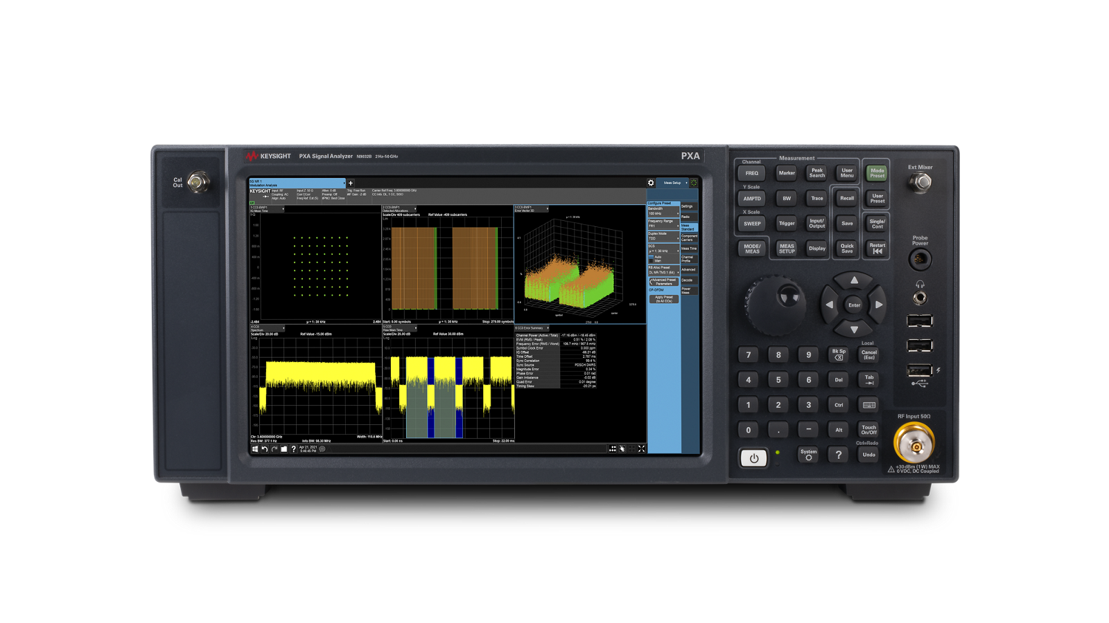





 粤公网安备44030902003758