是德科技 | KEYSIGHT
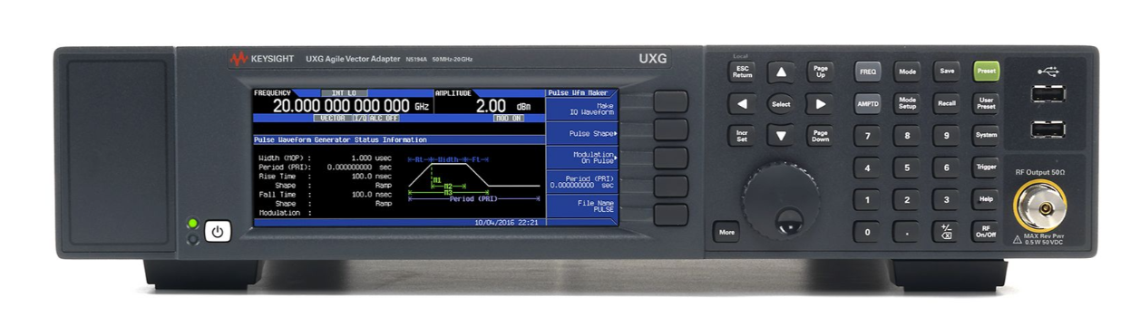
UXG系列N5191A 10MHz至20/40GHz捷变信号发生器 改进版 详细指标
精准模拟复杂信号场景
Specified range Tunable range
Option 52E 10 MHz to 20 GHz
10 MHz to 21.5 GHz
Option 54E 10 MHz to 40 GHz
10 MHz to 40 GHz
Phase continuous switching Minimizes phase changes and spectral splatter when transitioning to a new frequency within
条件:assuming the same setup conditions. Some temporary amplitude and phase changes may
Phase coherent switching When returning to a prior frequency, returns to the prior phase trajectory at that frequency,
Adjustable in 0.1° increments (nom)
条件:Accuracy is equivalent to the internal or external frequency reference in use.
Choices are the internal timebase reference oscillator, the external reference input, the
system sync input, and the
6 GHz input.
Internal timebase reference oscillator
Initial calibration accuracy ± 5 × 10
-8
Aging rate 1 ± 3 × 10 -8/year or ± 2.5 ×10 -10/day after
30 days
Temperature effects ± 4.5 × 10
-9 (nom) from 0 to 55 °C
Electronic frequency control (EFC) sensitivity
-0.04 ppm/V (nom) from -10 V to +10 V
External
10 MHz reference input
Modes Manually or automatically selected
条件:Input amplitude 6 dBm ± 6 dB (nom). To optimize phase noise use 6 dBm ± 2 dB (nom).
Lock range
± 1.0 ppm (nom)
Input impedance
50 Ω (nom)
System sync in/out See the Synchronization Section
6 GHz in/out See the Synchronization Section
Reference output (10/100 MHz output)
Frequency
10 MHz or 100 MHz, user selectable
Amplitude 7 dBm (nom) into
50 Ω load
1 Not verified by Keysight N7800A TME Calibration and Adjustment Software. Daily aging rate may be verified as a supplementary
chargeable service, on request
Frequency (GHz) 0.01 0.02 0.03 0.05 0.1 0.2 0.3 0.5 12 35 10 20 30
40
Region A0
Region A1
Region A2
Region A3
Region A4
Region A5
Region A6
Region A7
Region A8
Region A9
(N=1)
(N=1)
(N=2)
(N=4)
(N=8)
(N=16)1
(N=16)
(N=32)
(N=32)
条件:1. In Option 52E, the 18.8-21.5 GHz band behaves like it is part of Region A5.
In Option 54E, the 18.8-21.5 GHz band behaves like it is part of Region A6.
Extended Band Limits f or Modulation 10 − 13.5 MHz
10 MHz
12.8 MHz
19.4 MHz
29.4 MHz
44.5 MHz
67.5 MHz
102 MHz
155 MHz
235 MHz
356 MHz
540 MHz
818 MHz
1240 MHz
1.43 GHz
1.64 GHz
1.88 GHz
2.16 GHz
2.48 GHz
2.85 GHz
3.27 GHz
3.76 GHz
4.32 GHz
4.96 GHz
5.7 GHz
6.55 GHz
7.52 GHz
8.64 GHz
9.92 GHz
11.4 GHz
13.1 GHz
15 GHz
17.3 GHz
19.8 GHz
20.55 GHz
22.8 GHz
25.6 GHz
30.1 GHz
32 GHz
34.6 GHz
Frequency (GHz) 0.01 0.02 0.03 0.05 0.1 0.2 0.3 0.5 12 35 10 20 30
40
Region A0
Region A1
Region A2
Region A3
Region A4
Region A5
Region A6
Region A7
Region A8
Region A9
(N=1)
(N=1)
(N=2)
(N=4)
(N=8)
(N=16)1
(N=16)1
(N=32)
(N=32)
条件:1. In Option 52E, the 18.8-21.5 GHz band behaves like it is part of Region A5.
In Option 54E, the 18.8-21.5 GHz band behaves like it is part of Region A6.
Extended Band Limits f or Modulation 10 − 13.5 MHz
10 MHz
12.8 MHz
19.4 MHz
29.4 MHz
44.5 MHz
356 MHz
2.48 GHz
2.85 GHz
3.27 GHz
3.76 GHz
4.32 GHz
4.96 GHz
5.7 GHz
6.55 GHz
7.52 GHz
8.64 GHz
9.92 GHz
11.4 GHz
13.1 GHz
15 GHz
17.3 GHz
19.8 GHz
20.55 GHz
22.8 GHz
25.6 GHz
30.1 GHz
32 GHz
34.6 GHz
Default bands (Mode A) Provide lowest harmonics and spurious signals.
42.2 to 1980 MHz band (Mode B) Provides wider bandwidth at low frequencies for wider chirps, wider FM, and better pulse shape.
338 to 2610 MHz band (Mode B) Provides wider bandwidth at low frequencies for wider chirps, wider FM, and better pulse shape.
Dual attenuator specified frequency range (Option AT2)
Electronic agile attenuator 10 MHz to 20 GHz
10 MHz to 40 GHz
Mechanical step attenuator 10 MHz to 20 GHz
10 MHz to 40 GHz
Dual attenuator step size (Option AT2)
Electronic agile attenuator
0 dB to 65 dB in 5 dB steps, for frequencies up to 40 GHz, or bypassed
Mechanical step attenuator
0 dB to 85 dB in 5 dB steps, for frequencies up to 40 GHz
Maximum output power (Option
52E)
Frequency Standard Option AT2
Electronic attenuator bypassed
Electronic attenuator inline 10 MHz to 13 GHz 10 dBm 10 dBm
-1 dBm
> 13 GHz to 18 GHz 10 dBm 10 dBm
-4 dBm
> 18 GHz to 20 GHz 10 dBm 10 dBm
-6 dBm
Maximum output power (Option
54E)
Frequency Standard Option AT2
Electronic attenuator bypassed
条件:mechanical switches used to switch between bypass and inline modes can take as long as 20 ms (nom) to change modes.
Electronic attenuator inline 10 MHz to 13 GHz 10 dBm 8 dBm
-3 dBm
> 13 GHz to 18 GHz 10 dBm 8 dBm
-5 dBm
> 18 GHz to 20.55 GHz 7 dBm 6 dBm
-10 dBm
> 20.55 GHz to < 25.6 GHz 10 dBm 10 dBm
-7 dBm
25.6 GHz to 32 GHz 7 dBm 6 dBm
-8 dBm
> 32 GHz to 40 GHz 7 dBm 7 dBm
-7 dBm
1 Note that during EW simulations using option AT2 agile power capability, these are the maximum power values available in the
agile power range. Bypass mode is not recommended for EW simulations that require >
20 dB agile power capability, as the
Measured maximum output power (Opt
520)
−15
−10
−5
Without option AT2
Option AT2 with electronic attenuator bypassed
Option AT2 with electronic attenuator inline
-15
-10
-5
Measured maximum output power (Opt
540)
Without Option AT2
Option AT2 with electronic attenuator bypassed
Option AT2 with electronic attenuator inline
Frequency Standard Option AT2
Electronic attenuator bypassed
Electronic attenuator inline 10 MHz to 20 GHz -10 dBm -95 dBm
-130 dBm
> 20 GHz to 40 GHz (Option 540) -10 dBm -95 dBm
-130 dBm
Frequency Standard Option AT2
Electronic attenuator bypassed
Electronic attenuator inline
10 Hz to 20 GHz 20 dB (nom) 20 dB (nom)
90 dB (nom)
10 Hz to 18 GHz 20 dB (nom) 20 dB (nom)
90 dB (nom)
> 18 to 20.55 GHz 17 dB (nom) 20 dB (nom)
90 dB (nom)
> 20.55 to < 25.6 GHz 20 dB (nom) 10 dB (nom)
80 dB (nom)
> 25.6 GHz to 40 GHz 17 dB (nom) 10 dB (nom)
80 dB (nom)
条件:level with ALC off to match the power level with ALC on at a customer specified power level.
ALC off
1 No power leveling
ALC off with power alignment Power alignment is a routine that improves level accuracy with ALC off. It aligns the power
It should be run at regular intervals and whenever the operating temperature changes
± 5 °C
条件:Turns RF power on/off with external trigger 1 For EW simulations using option AT2 agile power capability, it is strongly recommended to operate with ALC mode off after running power alignment. If ALC mode is left on, switching speed performance will be significantly reduced.
-130
-110
-90
-70
-50
-30
-10
0.01 12345678 91 01 11 21 31 41 51 61 71 81 92
0
Agile Power Range for 20 GHz UXG
90 dB agile
-130
-110
-90
-70
-50
-30
-10 0.01 20.55 25.6
条件:Specifications apply for CW signals that do not exceed the maximum specified power. For instruments with Option 1ED Type-N connectors,
specifications apply below 18 GHz and performance is typically degraded 0.2 dB above 18 GHz.
Specifications apply for CW signals that do not exceed the maximum specified power.
Specifications apply for CW signals that do not exceed the maximum specified power.
significantly improved by running the UXG user amplitude correction routine with a power sensor.
2 Specifications apply after running power alignment at +4 dBm power level. It is strongly recommended that EW simulations
significantly reduced. 3 The Power Alignment routine aligns ALC off level accuracy performance to ALC ON performance at a customer specified power.
It should be run at regular intervals, and whenever the operating temperature changes ±5 °C from the alignment temperature.
alignment at a power level < 5 dBm and with the output attenuation set to the desired operating condition.
Agile power linearity (frequency ≤ 20 GHz with Option AT2) 1
Measured relative to -5 dBm for Option 52E and relative to -15 dBm for Option 54E with the mechanical step attenuator set to 0 dB and the
Measured relative to -15 dBm with the mechanical step attenuator set to 0 dB and the electronic attenuator inline.
Agile Power Range for 40 GHz UXG
90 dB agile
power range
80 dB agile power range
Amplitude resolution
0.01 dB
Level accuracy (Option 52E)
1
Output power (Standard) ALC on ALC off
3
10 dBm to 0 dBm ± 1.4 dB (typ)
± 2.0 dB (typ)
Output power (Option AT2) Mechanical attenuator Electronic attenuator ALC on ALC off
3
10 to 2 dBm 0 dB Bypass ± 1.5 dB
± 2.0 dB
< 2 to -10 dBm 0 dB Bypass ± 1.6 dB (typ)
± 2.5 dB (typ)
10 to -75 dBm Auto Bypass ± 1.5 dB
± 2.0 dB
-3 to -65 dBm 0 dB Inline ± 1.5 dB ± 2.0 dB
4
< -65 to -90 dBm 0 dB Inline ± 2.0 dB ± 2.5 dB
4
5 to -10 dBm Auto Auto ± 1.5 dB ± 2.0 dB
4
< -10 to -80 dBm Auto Auto ± 1.6 dB ± 2.5 dB
4
Level accuracy (Option 54E, frequency ≤ 20 GHz)
1
Output power (Standard) ALC on ALC off
3
10 dBm to 0 dBm ± 1.4 dB (typ)
± 2.0 dB (typ)
Output power (Option AT2) Mechanical attenuator Electronic attenuator ALC on ALC off
3
10 to 0 dBm 0 dB Bypass ± 1.5 dB
± 2.0 dB
< 0 to -10 dBm 0 dB Bypass ± 1.6 dB (typ)
± 2.5 dB (typ)
10 to -75 dBm Auto Bypass ± 1.5 dB
± 2.0 dB
-15 to -65 dBm 0 dB Inline ± 1.5 dB ± 2.0 dB
4
< -65 to -90 dBm 0 dB Inline ± 2.0 dB ± 2.5 dB
4
5 to -10 dBm Auto Auto ± 1.5 dB ± 2.0 dB
4
< -10 to -80 dBm Auto Auto ± 1.6 dB ± 2.5 dB
4
Level accuracy (Option 54E, frequency > 20 GHz)
1
Output power (Standard) ALC on ALC off
3
10 dBm to 0 dBm ± 1.4 dB (typ)
± 4.5 dB (typ)
Output power (Option AT2) Mechanical attenuator Electronic attenuator ALC on ALC off
3
10 to 0 dBm 0 dB Bypass ± 1.8 dB
± 4.5 dB
< 0 to -10 dBm 0 dB Bypass ± 1.6 dB (typ)
± 5.0 dB (typ)
10 to -50 dBm Auto Bypass ± 1.8 dB
± 4.5 dB
< -50 to -75 dBm Auto Bypass ± 2.2 dB
± 4.5 dB
-15 to -65 dBm 0 dB Inline ± 2.0 dB
± 4.5 dB
5 to -10 dBm Auto Auto ± 2.0 dB
± 4.5 dB
< -10 to -80 dBm Auto Auto ± 2.6 dB
± 4.5 dB
1 Specifications shown represent uncorrected performance at the RF output port. Level accuracy at the DUT input can be
be performed with ALC mode off after running power alignment. If ALC mode is left on, switching speed performance will be
For optimal performance in applications where the instrument will be used at more than one power level, execute power
4 For frequencies > 17 to 20 GHz, level accuracy degrades by an additional
0.5 dB.
electronic attenuator inline. 10 MHz to 13 GHz
± 0.4 dB (typ) for relative power from 0 to -75 dB
> 13 GHz to 20 GHz
± 0.5 dB (typ) for relative power from 0 to -75 dB
Agile power linearity (frequency > 20 GHz with Options 54E and AT2)
1
> 20 GHz to 40 GHz
± 1.8 dB (typ) for relative power from 0 to -60 dB
± 2.2 dB (typ) for relative power from -60 to -65 dB
条件:SWR (meas) with Option AT2, electronic attenuator bypassed, mechanical attenuator = 0 dB
SWR (meas) with Option AT2, electronic attenuator bypassed, mechanical attenuator > 0 dB
SWR (meas) with Option AT2, electronic attenuator inline
It should be run at regular intervals, and whenever the operating temperature changes ±5 °C from the alignment temperature.
alignment at a power level < 5 dBm and with the output attenuation set to the desired operating condition.
ALC on and frequency ≤ 20 GHz
± 0.02 dB/°C (typ)
ALC on and frequency > 20 GHz
± 0.04 dB/°C (typ)
ALC off and frequency ≤ 20 GHz
± 0.07 dB/°C (typ)
ALC off and frequency > 20 GHz
± 0.15 dB/°C (typ)
Output impedance
50 Ω (nom)
SWR (meas) without Option AT2
Frequency Option 52E with 1ED Option
54E
10 MHz to 1 GHz 1.4 : 1 1.4
1
> 1 GHz to 2 GHz 1.4 : 1 1.5
1
> 2 GHz to 18 GHz 1.7 : 1 2
1
> 18 GHz to 20 GHz 1.9 : 1 2
1
> 20 GHz to 40 GHz n/a
1
Frequency Option 52E without 1ED Option 52E with 1ED Option
54E
10 MHz to 1 GHz 1.4 : 1 1.4 : 1 1.4
1
> 1 GHz to 2 GHz 1.4 : 1 1.4 : 1 1.5
1
> 2 GHz to 18 GHz 1.7 : 1 1.7 : 1 2
1
> 18 GHz to 20 GHz 1.8 : 1 1.8 : 1 2
1
> 20 GHz to 40 GHz n/a n/a
1
Frequency Option 52E without 1ED Option 52E with 1ED Option
54E
10 MHz to 1 GHz 1.2 : 1 1.2 : 1 1.2
1
> 1 GHz to 2 GHz 1.2 : 1 1.2 : 1 1.2
1
> 2 GHz to 18 GHz 1.5 : 1 1.5 : 1 1.4
1
> 18 GHz to 20 GHz 1.5 : 1 1.5 : 1 1.4
1
> 20 GHz to 40 GHz n/a n/a 1.5
1
Frequency Option 52E without 1ED Option 52E with 1ED Option
54E
10 MHz to 1 GHz 1.6 : 1 1.6 : 1 1.6
1
> 1 GHz to 2 GHz 1.5 : 1 1.5 : 1 1.5
1
> 2 GHz to 18 GHz 1.7 : 1 1.7 : 1 1.7
1
> 18 GHz to 20 GHz 1.7 : 1 1.7 : 1 1.7
1
> 20 GHz to 40 GHz n/a n/a 1.8
1
1 The Power Alignment routine aligns ALC off level accuracy performance to ALC ON performance at a customer specified power.
For optimal performance in applications where the instrument will be used at more than one power level, execute power
Maximum reverse power 1/2 Watt
0 VDC
The User Corrections capability can apply corrections across frequency for amplitude, phase and time. Corrections can only be applied
when the UXG operates in Streaming Mode. Amplitude-only corrections can be done with a power sensor. In order to maximize agile
dynamic range, it may necessary to modify mechanical attenuator settings depending on PDW amplitude values and the peak amplitude
Number of points/table
2 to 3201
Number of tables Dependent on available free memory in instrument
10,000 maximum
Entry modes USB/LAN direct power meter control, LAN to GPIB and USB to GPIB, remote bus, and manual USB/
条件:amplitude with the lowest latency. When using the CC1 Interface Card, Option FR1 is required.
Fast CW Switching Mode The fast control port (Options CC1 or CC2) provides agile switching of CW frequency at a constant
Normal Mode The fast control port (Options CC1, CC3, or CC4) provides agile switching of frequency, phase,
amplitude, pulse modulation, frequency modulation, phase modulation, and chirp. Option CC2 provides
agile switching of frequency only
List Mode Internal list memory and a hardware trigger provide agile switching of frequency, phase, amplitude, pulse
modulation, frequency modulation, phase modulation, and chirp.
Streaming Mode The LAN interface or fast control port (Options CC1, CC3, or CC4) is asynchronous and utilizes
time stamps to provide agile switching of frequency, phase, amplitude, pulse modulation, frequency
modulation, phase modulation, and chirp. PDWs can also be streamed via the internal hard drive. Option
PM2 is required to stream.
Frequency transition types Transition examples
Type
1 A frequency change in which the initial frequency and final frequency
are in the same band per the frequency band diagrams in the frequency section, but not in region A0. 3.77 GHz to 4.3 GHz
35 GHz to 39 GHz
Type
2 A frequency change in which the initial frequency and final frequency
are in the same region per the frequency band diagrams in the
frequency section, but not in region A0.
1 GHz (A1) to 500 MHz (A1)
34 GHz (A9) to 40 GHz (A9)
Type
3 A frequency change in which the initial frequency and final frequency
are in regions A1 through A5 per the frequency band diagrams in the
frequency section. 1 GHz (A1) to 18 GHz (A5)
10 GHz (A4) to 3 GHz (A2)
Type 4 A frequency change not described in Types 1, 2, or 3.
1 GHz (A1) to 37 GHz (A9)
28 GHz (A8) to 10 GHz (A4)
22 GHz (A6) to 39 GHz (A9)
条件:For frequency and phase transitions at a fixed power level, with ALC off and the electronic attenuator bypassed, for frequencies < 32 GHz.
Measured from the first phase change of more than 0.1 radians that occurs after the input trigger, and measured to RF phase settled.
Applies to Normal Mode or List Mode, not Fast CW Switching Mode.
off. With Option AT2, includes amplitude changes over the agile power range.
Latency - Determined by transition time as measured from input trigger to RF phase and amplitude settled with ALC off. With Option AT2,
Transition type Standard Option SS3 (10 MHz to 6.89 GHz)
Type
100 μs (10 MHz to 31.6 GHz)
500 us (>
31.6 GHz to 40 GHz)
50 ns (typ)
Switching speed for Normal, Streaming, or List Mode
1
Update rate - Determined by transition time as measured from pulse sync out or list point start to RF phase and amplitude settled with ALC
Transition type Freq. Start/Stop Range Standard Option SS3
Type 1, 2, or
10 MHz to 6.89 GHz
10 MHz to 31.6 GHz
10 MHz to 40 GHz
100 μs
100 μs
500 μs
180 ns
100 μs
500 μs
10 MHz to 40 GHz
103 µs
503 μs
103 µs
503 μs
includes amplitude changes over the agile power range
Transition type Freq. Start/Stop Range Standard Option SS3
Type 1, 2 or
10 MHz to 6.89 GHz
10 MHz to 31.6 GHz
10 MHz to 40 GHz
101 μs
101 μs
501 μs
650 ns
101 μs
501 μs
10 MHz to 40 GHz
104 μs
504 μs
104 μs
504 μs
CW switching speed for Fast CW Switching Mode
2
Update rate - Determined by transition time as measured from pulse sync out to RF phase and amplitude settled at a fixed power level with
Transition type Freq. Start/Stop Range Standard Option SS3
Type 1, 2 or
10 MHz to 6.89 GHz
10 MHz to 31.6 GHz
10 MHz to 40 GHz
100 μs
100 μs
500 μs
240 ns
100 μs
500 μs
10 MHz to 40 GHz
103 μs
503 μs
103 μs
503 μs
Latency - Determined by transition time as measured from input trigger to RF phase and amplitude settled at a fixed power level with ALC
Transition type Freq. Start/Stop Range Standard Option SS3
Type 1, 2 or
10 MHz to 6.89 GHz
10 MHz to 31.6 GHz
10 MHz to 40 GHz
101 μs
101 μs
501 μs
370 ns
101 μs
501 μs
10 MHz to 40 GHz
104 μs
504 μs
104 μs
504 μs
Additional contributors to switching speed
条件:or CC4). Add 1 µs (nom) when switching to or from any frequency in region A0.
With GPIB, LAN, or USB control Add
900 μs (nom) from receipt of SCPI command or trigger signal
With Opt AT1 attenuators Add
20 ms (nom) for any change in the mechanical attenuator or bypass switch. These are controllable
via GPIB, LAN, or USB. These are not controllable via list or fast control port (Options CC1, CC2, CC3,
RF amplitude settling criteria
条件:end frequencies). 2 When using the CC1 Interface Card for Fast CW Switching, Option FR1 is required.
Measured to amplitude settled within
1 dB of final amplitude.
1 For list mode, each point is controlled by dwell time, which will be limited based on the larger of the two frequencies (start and
Multiple UXG units can be synchronized together to have phase coherent outputs. This is useful for simulating
angle-of-arrival (AoA) and phased array antenna wavefronts
条件:Synchronization input connections 10 MHz input Accepts a basic external reference at 10 MHz. Achieves lower residual phase noise than a 10 MHz input at the system sync input. See the Rear Panel Connectors Section for connection details.
important. Accepts a wide variety of input frequencies. See the Rear Panel Connectors Section for connection details.
Connectors Section for connection details. For a single N5191A, the 6 GHz output is fed into its own 6 GHz input.
Synchronization output connections 10/100 MHz output Provides a basic external reference at 10 MHz or 100 MHz. Achieves better spectral purity than the system sync.
Output power is +7 dBm 1 . See the Rear Panel Connectors Section for connection details.
System sync input Recommended external reference input for use in system environments where trigger jitter and phase stability are
6 GHz input Provides high stability synchronization between multiple signal generators. This is not a general
6 GHz connection. Only
the
6 GHz synchronization output from another compatible signal generator should be connected. See the Rear Panel
RF sync output Recommended external reference output for use in system environments where trigger jitter and phase stability are
important. Normally provides a 250 MHz output, but other frequencies are available. Output power is +11 dBm
1. See
the Rear Panel Connectors Section for connection details. 6 GHz output Provides high phase stability synchronization between multiple signal generators. Output power is +15 dBm
1. See the
条件:Usage The input frequency is not auto-detected. It must be entered manually and must be accurate to within the lock range above.
Frequency 1 to 250 MHz in 1 MHz steps. Default value is
250 MHz.
Lock range
± 1.0 ppm (nom)
Amplitude 6 dBm ± 6 dB (nom). To optimize phase noise use 6 dBm
± 2 dB (nom)
Input impedance
50 Ω (nom)
Frequency 10 MHz
100 MHz, or 250 MHz, selectable. Multi-box synchronization overrides this selection and may use other
条件:signal generator. The signal generator will not function without a 6 GHz signal at this input.
from a primary signal generator must be connected back into the 6 GHz input of the primary signal generator.
Output impedance
50 Ω (nom)
6 GHz input
Lock range
± 1.0 ppm (nom)
Amplitude 11 dBm
± 6 dB (nom)
Input impedance
50 Ω (nom)
Usage This input must be connected to the
6 GHz output (described below) or a similar output from another compatible
6 GHz output
Output impedance
50 Ω (nom)
Usage A rigid jumper cable is provided to connect the 6 GHz output to the
6 GHz input. The jumper can be removed
to distribute this signal to other equipment. When distributing this signal to multiple UXG signal generators,
approximately
12 dB of loss is permissible before distribution amplifiers are required. One of the distributed outputs
1 Does not include a guard band for performance distribution, measurement uncertainty, or environmental variations.
Normal mode is optimized for maximum update rate (throughput). If the fast control
port (FCP) Option CC1, CC3, or CC4 is installed, it provides the capability to use pulse
descriptor words (PDWs) to control frequency, amplitude, phase, pulse (include chirp
or phase coding), and FM or ϕM. With CC1, the PDW is streamed into the rear-panel
FCP 100-pin connector using
46-bit wide control words. The control word information is
Fast CW mode is optimized for minimum latency. The FCP control over signal attributes
is limited to CW frequency switching and the addition of FM/ ϕM provided this option
was purchased. It is typically used with the FCP Option CC2 for compatibility with
instruments used in legacy test systems. When using the CC1 Interface Card, Option
FR1 is required.
条件:or the Fast Control Port (with Option CC3 or CC4). The set of parameters controlled
Streaming provides agile control of most of the instrument settings via a continuous
stream of PDWs transferred from the internal SSD or an external source, such as a LAN
by Streaming include frequency, frequency band map, band adjust, relative power,
phase, phase mode, pulse, pulse start time, FM (chirp) and PM (phase coding). Each
PDW consists of seven
32-bit words. The streaming PDW parameters are executed
asynchronously, based on the time stamp information contained within the PDW. Option
PM2 is required to stream.
From file on solid state drive (SSD)
PDW streaming rate
750 k pulses/s (nom)
PDW streaming rate
750 k pulses/s (nom)
Over fast control port (FCP) (Options CC3/CC4)
PDW streaming rate
6 M pulses/s (nom)
Over CC4 10 GbE LAN Interface
1
PDW streaming rate
6 M pulses/s (nom)
PDW streaming trigger Auto, external, single, SCPI, timer, or trigger key
Pulse start time accuracy/ resolution 40 ps (typ)/
10 ps
Pulse fine delay accuracy/ resolution 40 ps (typ)/
10 ps
1 Typically requires driving the PDWs via a compiled language program.
List mode lets you play out a list of PDW’s located in and read from the instrument’s
FPGA memory. The memory contains a series of list points where each list point
contains multiple signal attributes. This mode supports dynamic sequencing using the
List of frequency, phase, amplitude, pulse, chirp, and modulation
Standard Advance every
100 μs to 34 s
Option SS3 Advance every
48 ns to 34 s (for frequencies from 10 MHz to 6.89 GHz)
Standard Advance every
100 μs to 17 s
Option SS3 Advance every
48 ns to 17 s (for frequencies from 10 MHz to 6.89 GHz)
Arbitrary list 1 to 500,000 per table assuming
50 sequences. Lists and sequences
Point trigger Auto, external, single, SCPI, timer, or trigger key
List trigger Auto, external, single, SCPI, timer, or trigger key
Sequence trigger Auto, external, single, SCPI, timer, or trigger key
Marker types List, sequence, point
Number of configurable markers Up to 12
Settable 标记参数 Polarity, 延迟
条件:Measured at 10 dBm or maximum specified power, whichever is lower. Performance is unspecified for harmonics beyond the specified
Fundamental frequency Harmonic level 10 MHz to 2.61 GHz (Frequency Mode B) -25 dBc (typ) 10 MHz to 1 GHz (Frequency Mode A)
-40 dBc
> 1 GHz to 2 GHz (Frequency Mode A)
-50 dBc
条件:Measured at +10 dBm or maximum specified power, whichever is lower. Sub-harmonics are defined as Carrier Freq *(x/N), where N
spurs which may overlap with sub-harmonics. Performance is unspecified for sub-harmonics beyond the specified frequency range.
indicates the frequency multiplication number and X is an integer value that is not an integer multiple of N. Does not apply to non-harmonic
Fundamental frequency 1/2
3/4, and 3/2 sub-harmonics Other sub-harmonics N
0.01 to < 1.43 GHz None None
1
1.43 to < 2.85 GHz -75 dBc -80 dBc
2
2.85 to < 5.7 GHz -75 dBc -80 dBc
4
5.7 to < 11.4 GHz -75 dBc -80 dBc
8
11.4 to < 16 GHz -70 dBc -80 dBc
16
16 to 20 GHz -65 dBc (typ) -70 dBc (typ)
16
> 20 to < 22.8 GHz (Opt 54E) -70 dBc (typ) -70 dBc (typ)
16
22.8 to 38 GHz (Opt 54E) -70 dBc (typ) -70 dBc (typ)
32
> 38 to 40 GHz (Opt 54E) - 62 dBc (typ) -70 dBc (typ)
32
Measured in Frequency Mode A at +10 dBm or maximum specified power, whichever is lower. Performance is unspecified for non-
Fundamental frequency Offsets >
300 Hz excluding power-
Power-line related 0.01 to < 1.43 GHz -70 dBc (typ) -60 dBc (typ) 1.43 to < 2.85 GHz -70 dBc (typ) -60 dBc (typ) 2.85 to < 5.7 GHz -70 dBc (typ)
-50 dBc (typ)
5.7 to < 11.4 GHz -70 dBc (typ)
-50 dBc (typ)
11.4 GHz to 20 GHz -70 dBc (typ)
-50 dBc (typ)
> 20 GHz (Opt 54E) 1 -65 dBc (typ)
-45 dBc (typ)
条件:In CW mode at +10 dBm or maximum specified output power, whichever is lower, for offsets > 10 MHz.
Frequency Broadband noise 10 MHz to 20 GHz
-131 dBc/Hz (typ)
> 20 GHz to 40 GHz (Opt 54E)
-125 dBc/Hz (typ)
1 At precisely 22 GHz, several spurs coalesce and may add to -60 dBc. Moving
1 Hz away from 22 GHz avoids this issue.
Phase noise is measured using a CW signal at +10 dBm or maximum specified power,
whichever is less, with spur optimizations off. Phase noise specifications exclude
条件:For frequencies from 400 MHz to 1.43 GHz, pulse modulation specifications apply in Mode B only. For
Frequency
20 kHz spec (typ)
0.01 to < 1.43 GHz
-132 (-135)
1.43 to < 2.85 GHz
-125 (-129)
2.85 to < 5.7 GHz
-119 (-122)
5.7 to < 11.4 GHz
-114 (-117)
11.4 to 20 GHz
-109 (-112)
> 20 GHz (Opt 54E)
-103 (-106)
Pulse modulation (Option PM2)
frequencies below
400 MHz, pulse modulation is not specified.
External input The RF pulse width is the same as the input pulse width at the pulse/trigger gate input
Triggered The internal pulse generator is triggered by a selectable trigger source. The pulse delay and
List 模式脉冲参数 defined · list
条件:Streaming mode The pulse parameters are defined in the streamed PDW data.
Free run The internal pulse generator generates pulses with the specified parameters without waiting
On/off ratio 0.4 to < 4.2 GHz 80 dB (90 dB typ) 4.2 GHz to 20 GHz
90 dB
> 20 GHz (Option 54E)
80 dB (90 dB typ)
Rise/fall times 0.4 to < 1.43 GHz (6 ns typ) 1.43 to < 2.85 GHz
10 ns (6 ns typ)
≥ 2.85 GHz
10 ns (3 ns typ)
ALC off
10 ns (10 MHz to 31.6 GHz)
32 ns (>
31.6 GHz to 40 GHz)
Minimum pulse repetition interval
ALC on
60 ns (10 MHz to 31.6 GHz)
64 ns (>
31.6 GHz to 40 GHz)
ALC off
20 ns (10 MHz to 31.6 GHz)
64 ns (>
31.6 GHz to 40 GHz)
Pulse start time accuracy/resolution
40 ps (nom)/10 ps
Pulse fine delay accuracy/ resolution
40 ps (nom)/10 ps
条件:For pulse width ≥ 100 ns with ALC on and for pulse width ≥ 10 ns with ALC off.
0.4 to < 1.43 GHz
± 1 dB (typ)
RF width relative to video out
± 5 ns (typ)
For frequencies ≥ 400 MHz and output power of 10 dBm or less
10% (typ)
External input to video output
60 ns (meas)
Frequency > 500 MHz
10 ns (meas)
+1 V = RF on
0 V = RF off
Input impedance
50 Ω (nom)
90%
条件:Option WC2 is required for chirp control through the Option CC1 I/O interface.
Frequency = 9 GHz, power = 10 dBm, amplitude = 10 dBm, ALC off, pulse width = 10 ns, pulse period =
100 ns. The oscilloscope is
protected by a
10 dB pad and the timescale is set to 2 ns/div.
Chirp and chirped-pulse modulation (Options UT1 and PM2)
1
Options installed Opt CC1 (LVDS) or
Opt CC3/CC4 (10 Gbit Ethernet)
Opt CC2 (BCD)
32 chirp slope selections above
6.89 GHz
FMCW available up to 6.89 GHz
3
UT1 + PM2 LFM within pulse up to 6.89 GHz
32 chirp slope selections within pulse
Chirped pulse not available
Chirped pulse up to 6.89 GHz
3
条件:CW mode. Option WC2 is required for wideband modulation, including chirp. Option PM2 is required for streaming mode.
3 Capability available with Firmware Revision A.01.70 with Option U03 or later.
Note: CW chirp (opt UT1 required) and Pulse Chirp (opt PM2 required) are available under the Pulse/Chirp hardkey in all modes except Fast
1 If FCP (Fast Control Port) state is set to on and real-time streaming control is used, chirp and chirped-pulse modulation is only
available for frequency range below
6.89 GHz.
2 When using the CC1 Interface Card for Fast CW Switching, Option FR1 is required.
Compatible without jitter Free-run, synchronously triggered
With ± 8 ns jitter Asynchronously triggered 26.5 GHz to 31.6 GHz (Option
54E)
Pulse and chirp alignment
条件:Deviation (peak to peak) with Option UT1
Option 52E cannot chirp beyond 21.5 GHz. Option 54E cannot chirp beyond 40 GHz.
Option 52E cannot chirp beyond 21.5 GHz. Option 54E cannot chirp beyond 40 GHz.
Wider deviations are available up to 6.89 GHz when not near a band edge, for example, any chirp which lies within one band is obtainable.
See the frequency band diagrams. Amplitude accuracy may degrade for wide chirps.
Chirp start time is aligned to pulse start time within
± 50 ns (typ)
Frequency Maximum peak to peak deviation 10 MHz to < 250 MHz 8 MHz 250 MHz to < 8 GHz 256 MHz 8 GHz to < 12 GHz
384 MHz
12 GHz to < 18 GHz
512 MHz
> 20 GHz to < 26.5 GHz (Option 54E)
768 MHz
≥ 26.5 GHz to 31.6 GHz (Option 54E) 1024 MHz
1
> 31.6 GHz to 40 GHz (Option 54E)
550 MHz
Deviation (peak to peak) with Options UT1 and WC2
Frequency Maximum peak to peak deviation 50 MHz to 6.89 GHz
10% of center frequency
> 6.89 GHz to 31.6 GHz (Option 54E) 2.2 GHz
1
> 31.6 GHz to 40 GHz (Option 54E)
550 MHz
Range
10 kHz/μs to 1.3 GHz/ns
Resolution
10 kHz/μs to 0.32768 kHz/ns depending on rate
1 Additionally, if chirp delta frequency is > 550 MHz or <
-550 Hz, then the chirp start and stop frequency (stop frequency = start
frequency + chirp delta) must both be ≤
32.35 GHz.
Internal pulse generator (Option PM2)
Modes Free-run, square, and triggered
Square wave rate
0.1 Hz to 10 MHz with 0.1 Hz resolution (nom)
Pulse period (PRI) (Tp)
30 ns to 42 s, corresponding to repetition frequencies of 0.024 Hz to 33.33 MHz. (10 MHz to 31.6 GHz)
32 ns to 42 s, corresponding to repetition frequencies of 0.024 Hz to 31.25 MHz. (>
31.6 GHz to 40 GHz)
Minimum pulse width (Tw)
4 ns (nom)
Pulse accuracy
40 ps (typ)
Frequency modulation (Option UT1)
条件:Maximum peak deviation with Option UT1
Option 52E cannot deviate beyond 21.5 GHz. Option 54E cannot deviate beyond 40 GHz.
Option 52E cannot deviate beyond 21.5 GHz. Option 54E cannot deviate beyond 40 GHz.
obtainable. See the frequency band diagrams. Amplitude accuracy may degrade for wide FM.
Internal or external
10 MHz
Frequency Maximum peak deviation 10 MHz to < 250 MHz 4 MHz 250 MHz to < 8 GHz 128 MHz 8 GHz to < 12 GHz
192 MHz
12 GHz to < 18 GHz
256 MHz
> 20 GHz to < 26.5 GHz (Option 54E)
384 MHz
≥ 26.5 GHz to 31.6 GHz (Option 54E)
512 MHz
> 31.6 GHz to 40 GHz (Option 54E)
275 MHz
Maximum peak deviation with Options UT1 and WC2
Frequency Maximum peak deviation 10 MHz to 6.89 GHz
5% of center frequency
> 6.89 GHz to 20 GHz
1.1 GHz
> 20 GHz to 31.25 GHz (Option 54E)
1.1 GHz
> 31.25 GHz to 31.6 GHz (Option 54E)
750 MHz
> 31.6 GHz to 40 GHz (Option 54E)
275 MHz
Wider deviations are available up to 6.89 GHz when not near a band edge, for example, any FM deviation which lies within one band is
Resolution
0.1% of deviation or 1 Hz, whichever is greater
Internal ± 1% of FM deviation (
± 0.2% typ)
External In ± 3.5% of FM deviation +
20 Hz
Modulation frequency response (3 dB bandwidth)
Measured at 100 kHz deviation.
DC to 10 MHz (nom)
5 Hz to 10 MHz (nom)
条件:At the calibrated deviation and carrier frequency, within 5 °C of ambient temperature at time of user calibration.
± 0.1% of set deviation (meas)
条件:Measured at a 1 kHz rate with 100 kHz deviation.
0.4%
Sensitivity
± 1 V peak for indicated deviation
Maximum pattern length 16 levels, at least 32 maps 4 ns
65,536 bits/pattern
Phase modulation (Option UT1)
Internal or external
10 MHz
Maximum peak deviation in radians 5% of carrier frequency
600 MHz or or 12 whichever is lessmodulation frequency modulation frequency π
Resolution
0.1% of set deviation
条件:Measured at a 1 kHz rate with 3π rad deviation.
Internal ± 1 % of ϕM deviation (
± 0.2% typ)
External In
± 3.5% of ϕM deviation
Modulation frequency response (3 dB bandwidth)
Measured at 3π rad deviation.
DC coupling DC to 10 MHz (nom)
AC coupling
5 Hz to 10 MHz (nom)
条件:Measured at a 1 kHz rate with 3π rad deviation.
Total harmonic distortion
0.5% (0.1% typ)
Sensitivity
± 1 V peak for indicated deviation
Triggered BPSK Phase can be changed 180˚ on a bin-by-bin basis every
8 ns via an external trigger
Supported Codes 2, 3, 4, 5, 7, 11
13
条件:performance is not specified with ALC off or above 20 GHz or when AM peaks exceed maximum specified power.
Maximum pattern length 16 levels, at least 32 maps 4 ns/4 ns
65,536 bits/pattern
Amplitude modulation (Option UT1)
AM performance is typical up to 20 GHz with ALC on when AM peaks do not exceed maximum specified power. AM
ALC on, 1 kHz rate and depth ≤ 80% ± (6% of setting +
1%)
External input (selectable polarity)
Sensitivity for indicated depth
1 Vpeak
Modulation frequency response (3 dB bandwidth)
Measured at 30% depth.
DC coupling DC to 10 MHz (nom)
AC coupling
5 Hz to 10 MHz (nom)
Distortion 30% AM, 1 kHz rate 1.5% total harmonic distortion 60% AM, 1 kHz rate
2% total harmonic distortion
External modulation inputs (Option UT1)
Connections Ext1 and Ext2
条件:Dual function generators Provide two independent signals (internal1 and internal2) for use with AM, FM, ϕM, or LF output.
Waveforms Sine, square, positive ramp, negative ramp, triangle, pulse, uniform noise, Gaussian noise.
Input impedance 50 Ω
600 Ω, or 1 MΩ (nom) switched
Internal modulation source (Option UT1)
Square, ramp, triangle
0.1 Hz to 1 MHz
条件:Also provides monitoring of function generators when used for AM, FM, or ϕM.
Output Internal 1, internal 2, noise generator 1, noise generator
2.
Amplitude 0 to 5 V peak (nom) into 50 Ω or 10 V (nom) into
1 MΩ
Output impedance
50 Ω (nom)
条件:Interfaces GPIB (IEEE-488.2,1987) with listen and talk, USB 2.0, and 1000BaseT LAN interface.
Control languages SCPI version 1997.0. Code compatibility modes for Aeroflex 2500, 2200, FS2000 or FS5000.
IEEE-488 functions SH1, AH1, T6, TE0, L4, LE0, SR1, RL1, PP0, DC1, DT0, C0, E2
Keysight IO libraries Keysight’s IO Library Suite helps you quickly establish an error-free connection between your PC and
instruments, regardless of the vendor. It provides robust instrument control and works with the software
development environment you choose
条件:Storage temperature range -40 to 70 °C; during storage below -20 °C, instrument states may be lost.
Humidity Maximum relative humidity (non-condensing): 95%RH up to 40 °C, decreases linearly to 45%RH at 55 °C 1
and verified to be robust against the environmental stresses of storage, transportation, and end-use.
line conditions. Test methods are aligned with IEC 60068-2 and levels are similar to MIL-PRF-28800F
Class 3. Phase noise specifications are not warranted in a vibrating environment.
Power requirements 100/120 VAC 50/60/400 Hz or 220/240 VAC
50/60 Hz (automatically selected)
< 350 W typical
400 W maximum
Operating temperature range
0 to 55 °C
Altitude
0 to 4600 m (15,000 ft)
Environmental testing Samples of this product have been tested in accordance with the Keysight Environmental Test Manual
Those stresses include but are not limited to temperature, humidity, shock, vibration, altitude, and power
ISO compliant This family of signal generators is manufactured in an ISO-9001 registered facility in concurrence with
Keysight’s commitment to quality
EMC Conforms to the immunity and emission requirements of IEC/EN
61326-1 including the conducted and
radiated emission requirements of CISPR Pub 11/2009 Group
1, Class A.
Acoustic noise Normal
48 dBA (nom)
Storage Memory is shared by instrument states and sweep list files.
The solid-state drive initially has at least
480 GB of free space.
Security Display blanking
Memory clearing functions (See Application Note, “Security Features of Keysight Technologies Signal
Generators,” Part Number E4400-90621).
acceptable limits, then the module passes the test
Weight <
25 kg (54 lb.) net
< 34 kg (73 lb.) shipping
Dimensions 134 mm H x 426 mm W x 559 mm D (5.25” H x 16.8” W x
22.0” D)
Recommended calibration cycle
12 months
1 From 40 °C to 55 °C, the maximum % Relative Humidity follows the line of constant dew point.
条件:Unless otherwise noted, all connectors are BNC female, digital inputs and outputs are 3.3 V CMOS, and digital
inputs will accept 5 V CMOS, 3 V CMOS, or TTL voltage levels. Option
1EM moves all connectors to the rear
条件:Option 54E Precision 2.4 mm male; plus 2.4 - 2.4 mm and 2.4 - 2.9 mm female adapters.
USB 2.0 primary (2 ports) Allows control of USB devices. USB Type-A female connector. Nominal output current 0.5 A.
LF output Outputs the internally generated LF source. Nominal output impedance 50 Ω.
External input 1 Drives either AM, FM, or ϕM . Nominal input impedance is 50 Ω, 600 Ω, or 1 MΩ, selectable.
External input 2 Drives either AM, FM, or ϕM . Nominal input impedance is 50 Ω, 600 Ω, or 1 MΩ, selectable. Damage
pulse modulation. Nominal impedance 50 Ω. Damage levels are 5 V rms and 10 V peak.
Pulse video out Outputs a signal that follows the RF output for internal pulse modes. TTL-level compatible. Nominal
RF output Output impedance
50 Ω (nom).
Option 52E Standard: Precision APC-3.5 male; plus
3.5 - 3.5 mm female adapter
Option
1ED: Type-N female; plus Type-N male - 3.5mm female adapter
Damage levels are
5 V rms and 10 V peak.
levels are
5 V rms and 10 V peak.
Pulse/trigger gate input Accepts input signal for external pulse modulation. Also accepts external trigger pulse input for internal
Pulse sync out Outputs a synchronizing pulse, nominally
50 ns width, for internal pulse modes. TTL-level compatible
nominal source impedance
50 Ω.
条件:Unless otherwise noted, all connectors are BNC female, digital inputs and outputs are 3.3 V CMOS, and digital
inputs will accept 5 V CMOS, 3 V CMOS, or TTL voltage levels. Option
1EM moves the front panel connectors to
GPIB Operates as a GPIB controller or device. IEEE-488 bus connector.
LAN (1000 BaseT) Allows LAN TCP/IP communication. RJ45 Ethertwist connector. The LAN connector provides the same
SCPI remote programming functionality as the GPIB connector. The LAN connector is a used to access
the internal web server and FTP server. The LAN supports DHCP , HiSLIP , sockets SCPI, VXI-11 SCPI,
connection monitoring, dynamic hostname services, and TCP keep alive. This interface is LXI class C
条件:USB 2.0 primary (2 ports) Allows control of USB devices. USB Type-A female connector. Nominal output current 0.5 A.
USB 2.0 secondary (1 port) Receives control from USB host. USB Type-B female connector. Nominal output current 0.5 A.
10 MHz input Accepts a 10 MHz external reference (timebase) input. Nominal input impedance 50 Ω. Nominal input
10/100 MHz output Provides a reference signal of 10 MHz or 100 MHz, selectable. Nominal output impedance 50 Ω. Output
signal generator. 10 MHz EFC Accepts an external DC voltage, ranging from -10 V to +10 V, for electronic frequency control (EFC) of the internal 10 MHz reference oscillator. This voltage inversely tunes the oscillator about its center frequency.
See the EFC sensitivity in the frequency section. The nominal input impedance is greater than 1 MΩ.
System sync input Accepts an external reference input. The acceptable frequencies are listed in the synchronization section.
Nominal input impedance 50 Ω, with a DC block. Nominal input range 0 to 12 dBm.
RF sync output Provides an external reference output of 10, 100, or 250 MHz, or Sync Output, selectable. Nominal
6 GHz input SMA female connector. Accepts a synchronization input of 6 GHz. Nominal input impedance 50 Ω.
Nominal input range 5 to 17 dBm. Damage levels are above +23 dBm.
6 GHz output SMA female connector. Provides a synchronization output of 6 GHz. Nominal output impedance 50 Ω.
PCIe x8 Provides
8 lanes of PCIe I/O. Reserved for future use.
power is +7 dBm 1. Suitable for use with the
10 MHz input or System Sync input of another compatible
1 Does not include a guard band for performance distribution, measurement uncertainty, or environmental variations.
output impedance
50 Ω. Suitable for use with the System sync input. This output is a square wave with
a fast rise time. To avoid electromagnetic interference, use coaxial cable with at least
90 dB shielding
effectiveness. Example: Times Microwave Systems LMR 240 coaxial cable used in Amphenol PN
115101-
22-48.00 BNC cable assembly. Output power is +11 dBm
1.
Output power is +15 dBm 1. Suitable for use with the
6 GHz input.
Triggers
1-14 Number of trigger varies depending on which option is installed (CC1, CC2, CC#, or CC4). These use
3.3V CMOS levels and are tolerant to 5V inputs. The output impedance is
50 Ω and the input is high
以上指标摘自厂家官方数据手册,完整定义、测试条件与保证值口径以手册为准。完整指标、测试条件与定义口径请见产品页「软件和手册 | 白皮书」栏目中的官方数据手册。
是德科技 | KEYSIGHT · onetest 仪器资源库


 客服












 粤公网安备44030902003758