是德科技 | KEYSIGHT
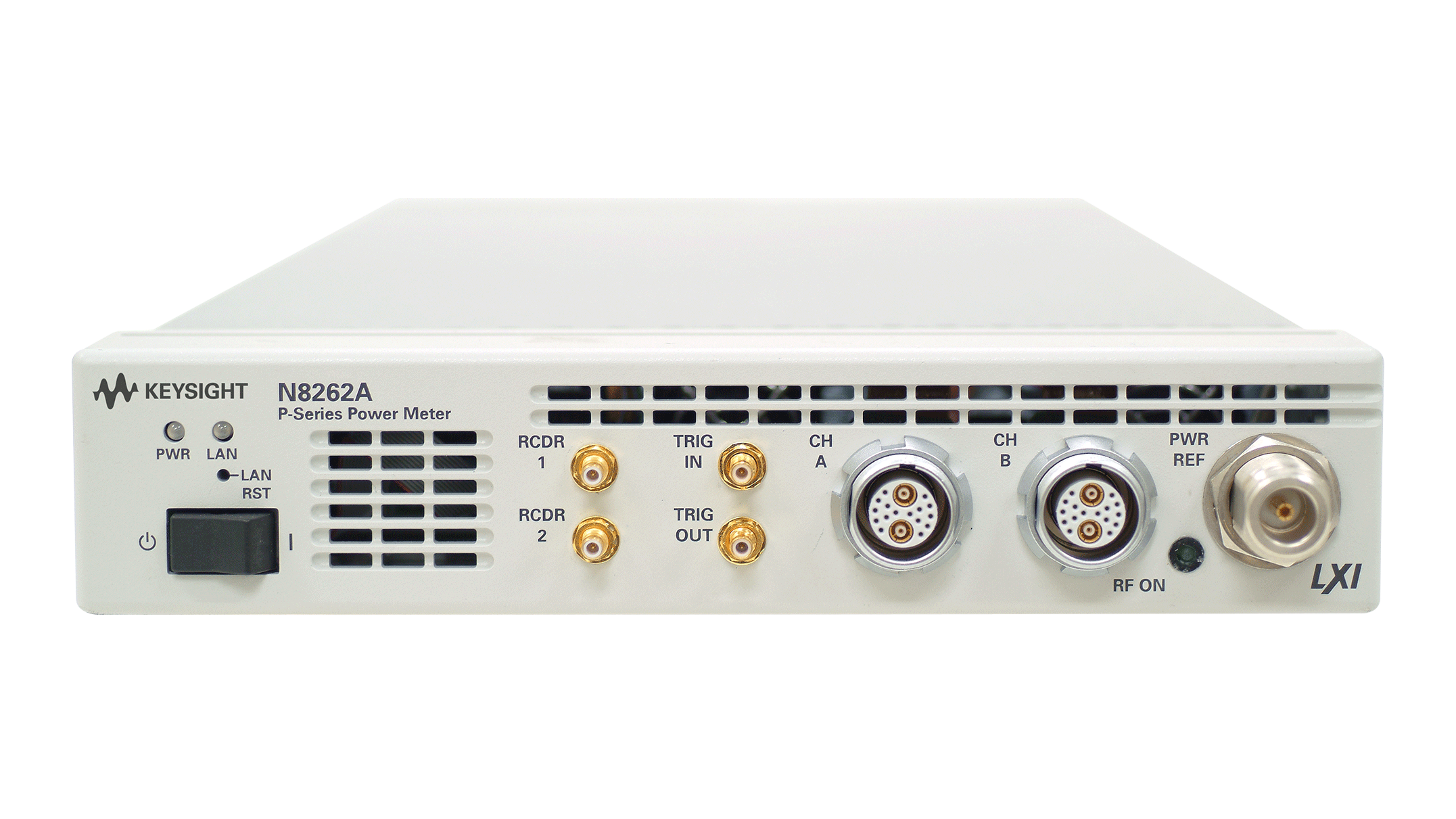
P系列N8262A 模块化功率计(符合 LXI 标准) 详细指标
用于复杂脉冲和调制信号的功率测量
一、Warranted Specifications
条件:0 to 55 ºC unless otherwise noted. Warranted specifications include measurement uncertainty
Warranted specifications are specifications which are covered by the product warranty and apply over
calculated with 95% confidence.
Characteristic specifications are specifications that are not warranted. They describe product
performance is useful in the application of the product. These characteristic specifications are shown in
Characteristic information is representative of the product. In many cases, it may also be supplemental
Characteristic specifications are not verified on all units. There are several types of characteristic
specifications. These types can be placed in two groups
条件:‘nominal’. These two terms are most widely used when describing a product’s ‘attributes’.
The second group describes ‘statistically’ the aggregate performance of the population of products.
for in the specification. These specifications are referred to as ‘typical’.
One group of characteristic types describes ‘attributes’ common to all products of a given model or
option. Examples of characteristics that describe ‘attributes’ are product weight, and 50 ohm input Type-
N connector. In these examples’ product weight is an ‘approximate’ value and a
50 ohm input is
These characteristics describe the expected behavior of the population of products. They do not
guarantee the performance of any individual product. No measurement uncertainty value is accounted
The power meter and sensor will meet its specifications when:
• Store for a minimum of two hours at a stable temperature within the operating temperature range, and
turn on for at least
30 minutes
• The power meter and sensor are within their recommended calibration period, and
• Used in accordance with the information provided in the N8262A P-Series Modular Power Meter
Using the N8262A P-Series power meter with BenchVue software
The N8262A P-Series power meter is supported by Keysight BenchVue software’s BV0007B Power
Meter/Sensor Control and Analysis app. Keysight BenchVue software for the PC accelerates testing by
providing intuitive, multiple instrument measurement visibility and data capture with no programming
necessary. You can derive answers faster than ever by easily viewing, capturing and exporting
条件:definition. Time parameter measurements of pulse rise time, fall time, pulse width, time to positive
1. Information contained in this document refers to operation with P- Series power sensors. For specifications when used with 8480 and
E-Series power sensors (except E9320 range), refer to Lit Number 5965- 6382E.
Frequency range N1921A P-Series wideband power sensor
50 MHz to 18 GHz
N1922A P-Series wideband power sensor
50 MHz to 40 GHz
Measurements Average, peak and peak-to-average ratio power measurements are provided with free-run or time gated
occurrence and time to negative occurrence are also provided.
Sensor compatibility P-Series modular power meter is compatible with all Keysight P-Series wideband power sensors, E-Series
power sensors (except E9320 range) and 8480 Series power sensors
1.
P-Series Modular 功率 Meter 和传感器
条件:Figure 1. Measured rise time percentage error versus signal under test rise time.
the root sum of the squares (RSS) of the signal under test rise time, and the system rise time (13 ns):
Measured rise time = √ ((signal under test rise time) 4 + (system rise time) 4), and the % error is:
1. Specification applies only when the Off video bandwidth is selected.
2. The Minimum Pulse Width is the recommended minimum pulse width viewable on the power meter, where power measurements
are meaningful and accurate, but not warranted. 3. Specification is valid over –15 to +20 dBm, and a frequency range 0.5 to 10 GHz, DUT Max. SWR < 1.27 for the N1921A, and a frequency range 0.5 to 40 GHz, DUT Max. SWR < 1.2 for the N1922A. Averaging set to 32, in Free Run mode. 4. See Appendix A on page 9 for measurement uncertainty calculations.
Key system specifications and characteristics
2
Maximum sampling rate
100 Msamples/sec, continuous sampling
Single shot bandwidth ≥
30 MHz
Rise time and fall time ≤ 13 ns (for frequencies ≥ 500 MHz) 1, see Figure
1
Minimum pulse width 50 ns
2
Average power measurement accuracy N1921A: ≤ ± 0.2 dB or ± 4.5%
3
N1922A: ≤ ± 0.3 dB or
± 6.7%
Dynamic range –35 to +20 dBm (>
500 MHz)
–30 to +20 dBm (50 to 500 MHz)
Maximum capture length
1 second
Maximum pulse repetition rate 10 MHz (based on
10 samples per period)
Although the rise time specification is ≤
13 ns, this does not mean that the P-Series meter and sensor
combination can accurately measure a signal with a known rise time of 13 ns. The measured rise time is
• % Error = ((measured rise time – signal under test rise time)/signal under test rise time) x
100
三、P-Series Modular Power Meter Specifications
Instrumentation linearity
± 0.8%
Timebase range
2 ns to 100 msec/div
• Latency 1 160 ns
± 10 ns
Minimum trigger pulse width
15 ns
Minimum trigger repetition period
50 ns
Maximum trigger 15 V emf from 50 Ω dc (current <
100 mA), or
• Voltage input 60 V emf from 50 Ω dc (pulse width < 1 s, current <
100 mA)
External TTL trigger output Low to high transition on trigger event
Delay range
± 1.0 s, maximum
Delay resolution 1% of delay setting
10 ns maximum
Resolution
1% of selected value (to minimum of 10 ns)
Trigger level threshold hysteresis
条件:1. Internal trigger latency is defined as the delay between the applied RF crossing the trigger level and the meter switching into the
triggered state. 2. External trigger latency is defined as the delay between the applied trigger crossing the trigger level and the meter switching into the triggered state. 3. External trigger output latency is defined as the delay between the meter entering the triggered state and the output signal
四、P-Series Wideband 功率传感器规格
The P-Series wideband power sensors are designed for use with the P-Series power meters N1911/12A
and the P-Series modular power meter N8262A only.
Sensor model Frequency range Dynamic range Damage level Connector type
N1921A 50 MHz to 18 GHz –35 dBm to +20 dBm (≥ 500 MHz)
+23 dBm (average power) Type N (m)
–30 dBm to +20 dBm (50 to 500 MHz) +30 dBm (<
1 μs duration) (peak power)
N1922A 50 MHz to 40 GHz –35 dBm to +20 dBm (≥ 500 MHz) +23 dBm (average power)
2.4 mm (m)
–30 dBm to +20 dBm (50 to 500 MHz) +30 dBm (<
1 μs duration) (peak power)
Sensor Calibration Uncertainty
1
500 MHz to 1 GHz 4.0%
4.2%
Dimensions (Length x Width x Height) in mm with +/-
1 mm
条件:1. Beyond 70% Humidity, an additional 0.6% should be added to these values.
Weights with cable Option 105
0.4 kg
Fixed sensor cable lengths Option 105
1.5 m (5-feet)
Option 106
3.0 m (10-feet)
Recommendation calibration interval
1 year
条件:performance. At no time should the pin depth of the connector be protruding.
Mechanical characteristics such as center conductor protrusion and pin depth are not performance
specifications. They are; however, important supplemental characteristics related to electrical
1 mW Power Reference
Note. The
1 mW power reference is provided for calibration of E-Series (except E9320 range) and 8480
Series power sensors. The P-Series sensors are automatically calibrated and do not need this reference
Power output 1.00 mW (0.0 dBm). Factory set to
± 0.4% traceable to the National Physical Laboratory
Accuracy (over 2 years)
± 1.2% (0 to 55 ºC)
1.05 typical
Connector type Type N (f)
50 Ω
Recorder output(s) Analog 0 to 1 volt 1 kΩ output impedance. There are two recorder outputs with SMB
Trigger input Input has TTL compatible logic levels and uses a SMB connector
Rear panel inputs/outputs
100BaseT LAN Interface allows communication with an external controller
Ground Binding post, accepts
4 mm plug or bare-wire connection
• Input voltage range 100 to 120 V
± 10%
• Input frequency range 50 to 60 Hz
± 10% (all voltages)
400 to 440 Hz (100 to 120 V only)
• Power requirement Not exceeding
75 VA (50 Watts)
Interface
10/100BaseT LAN interface
Measurement speed via remote interface ≥
1500 readings per second
Electromagnetic compatibility Comply with the requirements of the EMC Directive
89/336/EEC
Product safety Conforms to the following product specifications:
• IEC 61326-1:1997+A1:1998/EN
61326-1:1997+A1:1998
• CISPR 11:1990/EN
55011:1991
• Canada: CSA C22.2 No.
61010-1:2004
• USA: UL:61010-1:2004
条件:Dimensions in mm with +/- 1 mm The following dimensions exclude front and rear panel protrusions:
44.2 mm H x 212.6 mm W x 420.3 mm D (1.75 in x 8.5 in x
19.63 in)
Net weight ≤
3.5 kg (7.7 lb) approximate
Shipping weight ≤
7.7 kg (17.0 lb) approximate
General Comply with the requirements of the EMC Directive
89/336/EEC.
条件:Maximum humidity 95% at 40 °C (non-condensing)
Minimum humidity 15% at 40 °C (non-condensing)
Maximum altitude
3,000 meters (9,840 feet)
条件:Non-operating maximum humidity 90% at 65 °C (non-condensing)
Non-operating storage temperature
–40 to +70 °C
Non-operating maximum altitude
15,420 meters (50,000 feet)
Recommendation calibration interval
1 year
The video bandwidth in the power meter can be set to High, Medium, Low or Off. The video bandwidths
stated in the table below are not the
3 dB bandwidths, as the video bandwidths are corrected for optimal
flatness (except the Off filter). Refer to Figure 2 for information on the flatness response. The Off video
bandwidth setting provides the warranted rise time and fall time specification and is the recommended
Dynamic response - rise time, fall time, and overshoot versus video bandwidth settings
条件:For Option 107 (10 m cable), add 5 ns to the rise time and fall time specifications.
1. Specified as 10% to 90% for rise time and 90% to 10% for fall time on a 0 dBm pulse.
2. Specified as the overshoot r For Option 107 (10 m cable), add 5 ns to the rise time and fall time specifications r elative to the
Low: 5 MHz Medium: 15 MHz High
30 MHz Off
Rise time/fall time 1 < 56 ns < 25 ns ≤ 13 ns < 36 ns ≤
13 ns
Overshoot 2 < 5 % <
5 %
The recorder output is used to output the corresponding voltage for the measurement that user sets on
条件:The video output is the direct signal output detected by the sensor diode, with no correction applied.
The video output provides a DC voltage proportional to the measured input power through a BNC
connector on the rear panel. The DC voltage can be displayed on an oscilloscope for time
measurement. This option replaces the recorder output on the rear panel. The video output impedance
The peak flatness is the flatness of a peak-to-average ratio measurement for various tone-separations
for an equal magnitude two-tone RF input. Figure
2 refers to the relative error in peak-to-average ratio
measurements as the tone separation is varied. The measurements were performed at –10 dBm with
power sensors with 1.5 m cable lengths.
Figure
2. N192XA Error in peak-to-average measurements fo r a two-tone input (High, Medium, Low or Off filters)
Sensor model Zeroing Zero set Zero drift 1 Noise per sample Measurement noise (Free run)
2
条件:1. Within 1 hour after a zero, at a constant temperature, after 24- hour warm -up of the power meter. This component can be
disregarded with Auto- zero mode set to ON . 2. Measured over a one- minute interval, at a constant temperature, two standard deviations, with averaging set to 1.
No RF on input ± 200 nW ± 200 nW 100 nW 2 μW
50 nW
RF present ± 550 nW
± 200 nW
Measurement average setting 1 2 4 8 16 32 64 128 256 512
1024
Free run noise multiplier 1 0.9 0.8 0.7 0.6 0.5 0.45 0.4 0.3 0.25
0.2
Video BW setting Low 5 MHz Medium 15 MHz High
30 MHz Off
Noise per sample multiplier < 500 MHz 0.5 1 2
1
条件:Low). If averaging is implemented, this will significantly impact the effect of changing the video bandwidth.
The noise per sample is reduced by applying the meter video bandwidth filter setting (High, Medium or
The measurement noise on a time-gated measurement will depend on the time gate length.
100
averages are carried out every 1 us of gate length. The Noise-per-Sample contribution in this mode can
approximately be reduced by √(gate length/10 ns) to a limit of 50 nW.
N8262A P-Series modular power meter (LXI-C compliant)
N192xA-105 P-Series sensors fixed
1.5 m (5 ft) cable length
N192xA-106 P-Series sensors fixed
3 m (10 ft) cable length
N192xA-107 P-Series sensors fixed
10 m (31 ft) cable length
N1917A P-series meter cable adaptor
1.5 m (5 ft)
N1917B P-Series meter cable adaptor
3 m (10 ft)
N1917C P-Series meter cable adaptor
10 m (31 ft)
N1917D P-Series meter cable adaptor
1.8 m (6 ft)
N191xA-200
11730x cable adaptor
Other accessories Description 34131A Transit case for half-rack 2U-high instruments (e.g.
34401A)
N8262A-908 Rack mount kit (one instrument)
N8262A-909 Rack mount kit (two instruments)
BV0007B BenchVue Power Meter/Sensor Control and Analysis app license
N8262A-1A7 ISO17025 calibration data including Z540 compliance
N8262A-A6J ANSI Z540 compliant calibration test data
R-50C-011-3 Calibration Assurance Plan - Return to Keysight - 3 years
R-50C-011-5 Calibration Assurance Plan - Return to Keysight - 5 years
R-50C-021-3 ANSI Z540-1-1994 Calibration up front - 3 years plan
R-50C-021-5 ANSI Z540-1-1994 Calibration up front - 5 years plan
Uncertainty calculations for a power measurement (settled, average power)
(Specification values from this document are in bold italic, values calculated on this page are underlined.)
Calculate noise contribution
条件:— Convert noise contribution to a relative term 1 = Noise/Power ..................................
— Instrumentation linearity ..........................................................................................
— Drift .............................................................................................................................
— RSS of above three terms => Meter uncertainty = .....................................................
Zero uncertainty (Mode and frequency dependent) = Zero set/Power = .....................................................
Sensor calibration uncertainty (Sensor, frequency, power and temperature dependent) = ...........................................
System contribution, coverage factor of 2 ≥ sysrss = .........................................................
Standard uncertainty of mismatch .....................................................................................
Max SWR (frequency dependent) =................................................................................
— If in Free Run mode, Noise = Measurement noise x free run multiplier
— If in Trigger mode, Noise = Noise-per-sample x noise per sample multiplier
(RSS three terms from steps
4 and 5)
以上指标摘自厂家官方数据手册,完整定义、测试条件与保证值口径以手册为准。完整指标、测试条件与定义口径请见产品页「软件和手册 | 白皮书」栏目中的官方数据手册。
是德科技 | KEYSIGHT · onetest 仪器资源库


 客服










 粤公网安备44030902003758