

 客服




输出频率范围:100 kHz 至 6 GHz
残余相位噪声:< -100 dBc/Hz @ 10kHz, 1 GHz
调整分辨率:1赫兹
IF带宽:80/160/320 MHz
三阶互调高达: < 75dBc(0 dBm输出电平)
ONETEST 欢迎您
厂商登录 | 入驻
登录 | 注册 购物车 微信公众号厂商登录

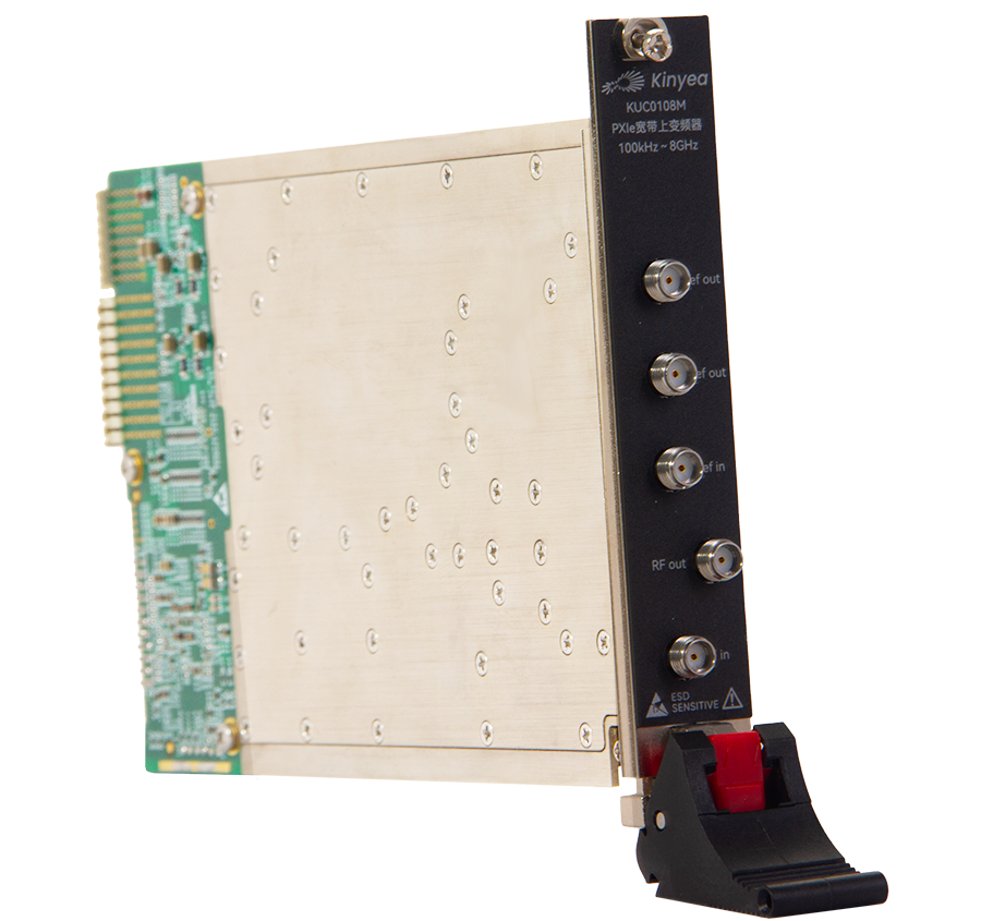
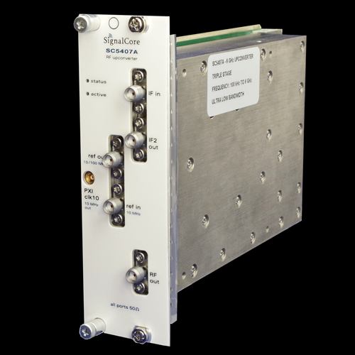
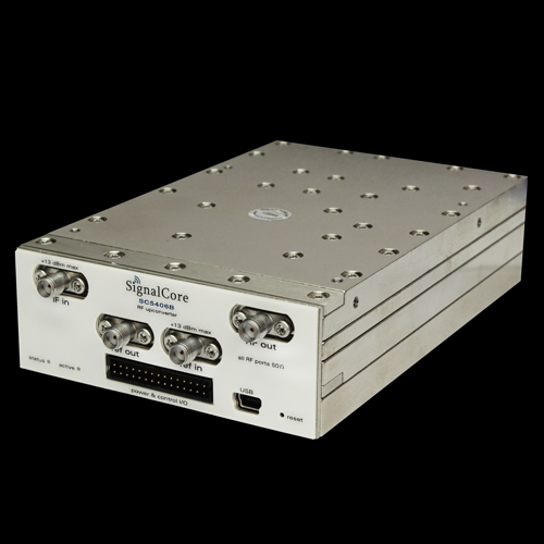
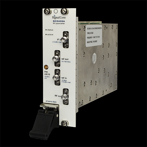
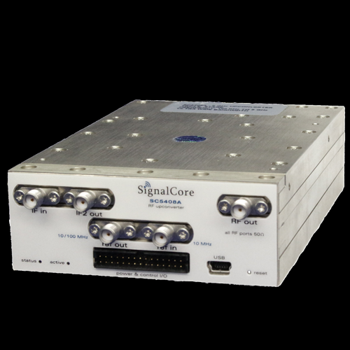
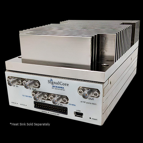
输出频率范围:100 kHz 至 6 GHz
残余相位噪声:< -100 dBc/Hz @ 10kHz, 1 GHz
调整分辨率:1赫兹
IF带宽:80/160/320 MHz
三阶互调高达: < 75dBc(0 dBm输出电平)
SC5408A 100kHz至6GHz模块式射频上变频器|SignalCore
Spectral Specifications
RF output range
Direct path....................................................................................................................... 100 kHz to 400 MHz
Conversion path ................................................................................................................ 20 MHz to 6.0 GHz
IF2 output frequency .......................................................................................................................................... 1.25 GHz
IF input center frequency 1
First (IF3) stage conversion enabled..................................................................... 50 MHz to 500 MHz
Second IF selected (Bypass IF3 conversion).............................................................................1.25 GHz
RF output polarity 2 First (IF3) stage conversion enabled.............................................................. Non-inverted/Inverted
Second IF selected (Bypass IF3 conversion)..............................................................................Inverted
IF bandwidth (3 dB)
First (IF3) stage conversion enabled................................................................................... 80/160 MHz (Contact SignalCore for other IF BW options 1 )
IF3 conversion bypassed (2 stage conversion)....................................................................... 320 MHz
RF tuning
Frequency step resolution 3 ........................................................................................................................ 1 Hz
Lock and settling times 4 .............................................................................................................................. 1 ms
Frequency reference 5
Technology ............................................................................... Temperature compensated crystal oscillator
Accuracy ................................ ± [(aging x last adjustment time lapse) + temp stability + cal accuracy]
Initial calibration accuracy ..................................................................................................................... ±0.05 ppm
Temperature stability 6
20 °C to 30 °C ........................................................................................................................................ ±0.25 ppm
0 °C to 55 °C .............................................................................................................................................. ±1.0 ppm
Aging .......................................................................................................................... ±1 ppm for first year @ 25 °C
Frequency accuracy 7 .................................. ± (frequency reference accuracy * RF output frequency) Hz
| Sideband noise (dBc/Hz)8 | ||||
| RF Frequency | ||||
| Offset | 100 MHz | 2000 MHz | 4000 MHz | 5500 MHz |
| 100 Hz | -80 | -78 | -76 | -74 |
| 1 kHz | -95 | -93 | -91 | -89 |
| 10 kHz | -100 | -97 | -95 | -93 |
| 100 kHz | -112 | -110 | -110 | -109 |
| 1 MHz | -139 | -138 | -138 | -137 |
| 10 MHz | -148 | -147 | -144 | -143 |
LO related sideband spurious signals 10
< 200 kHz ...................................................................................................................................................... -70 dBc
> 200 kHz ...................................................................................................................................................... -75 dBc
Amplitude Specifications
IF Input range
AC ................................................................................................................................................................ +17 dBm max
DC 11 .................................................................................................................................................................................. 0 V
Attenuation range
RF ....................................................................................................................................................0 to 60 in 1 dB steps
IF 12 ................................................................................................................................................ 0 to 60 in 1 dB steps
Output voltage standing wave ratio (VSWR)
10 MHz to 3.0 GHz .................................................................................................................................................. < 2.0
3.0 GHz to 6.0 GHz .................................................................................................................................................. < 2.8
Gain (@ 1GHz) 13
Minimum 14............................................................................................................................................... -90 dB typical
Maximum 15 .............................................................................................................................................. 30 dB typical
RF amplitude response (15 °C to 35 °C ambient)
RF gain flatness response (uncorrected) ..................................................................................... 14 dB typical
RF gain flatness response (corrected16) ................................................................................................ ±0.75 dB
Absolute gain accuracy (corrected16) .................................................................. ±1.0 dB (±0.75 dB typical)
IF flatness (15 °C to 35 °C ambient)
IF in-band response flatness ................................................................................................................ 3 dB typical
IF to RF group delay (80% of IF bandwidth)
3 stage conversion ................................................................................................................................ 100 ns typical
2 stage conversion ................................................................................................................................ 100 ns typical
Spurious response 17
Spurious signals 18 ..........................................................................................................................................< -65 dBc
LO leakage 19 .....................................................................................................................................................< -65 dBc
| Output Signal-to-Noise(15 ℃ to 30 ℃ ambient)20 | |||
| 100 MHz | 3000 MHz | 5500 MHz | |
| Best SNR setting 21 | 148 dB/Hz | 147 dB/Hz | 140 dB/Hz |
| Best linearity setting 22 | 126 dB/Hz | 124 dB/Hz | 120 dB/Hz |
| Output third-order intermodulation (OIP3,dBm)23 | |||
| 100 MHz-1.5 GHz | 1.5 GHz-4 GHz | 4 GHz-6 GHz | |
| Best SNR setting 21 | 17 | 17 | 15 |
| Best linearity setting 22 | 32 | 31 | 29 |
| Output second harmonic (dBm @0 dBm Output) | ||||
| 500 MHz | 1000 MHz | 2700 MHz | ||
| Harmonic level | -60 | -55 | -52 | |
| Output compression point (dBm) | ||||
| 100 MHz-1.5 GHz | 1.5 GHz-4.0 GHz | 4.0 GHz-6.0 GHz | ||
| IF3 mixer level =0 dB | >18 | >17 | >15 | |
Reference Input and Output Specifications
Reference output specifications
Center frequency 24 ...................................................................................................................... 10 MHz/100 MHz
Amplitude ....................................................................................................................................................... 3 dBm typ
Waveform .................................................................................................................................................................... Sine
Impedance ............................................................................................................................................... 50 nominal
Coupling ........................................................................................................................................................................... AC
Connector type .......................................................................................................................................... SMA female
Frequency accuracy ................................................................................ See “Spectral Specifications” section
Reference input specifications
Center frequency .............................................................................................................................................. 10 MHz
Amplitude ...................................................................................................................... 0 dBm min/ +10 dBm max
Phase-lock range ................................................................................................................................... ± 3 ppm (typ)
Impedance ............................................................................................................................................... 50 nominal
Coupling ........................................................................................................................................................................... AC
Connector type .......................................................................................................................................... SMA female
Port Specifications
RF output
Output impedance .................................................................................................................................................. 50
Coupling ........................................................................................................................................................................... AC
Connector type .......................................................................................................................................... SMA female
IF input
Input impedance ..................................................................................................................................................... 50
VSWR ............................................................................................................................................................................... 1.8
Coupling ........................................................................................................................................................................... AC
Connector type .......................................................................................................................................... SMA female
Output amplitude ................................................................................................................................... 20 dBm max
Environmental
Operating temperature 25 .................................................................................................................. 0 °C to +55 °C
Storage temperature ....................................................................................................................... -40 °C to +70 °C
Operating relative humidity ............................................................................. 10% to 90%, non-condensing
Storage relative humidity .................................................................................... 5% to 90%, non-condensing
Operating shock ...................................................................................... 30 g, half-sine pulse, 11 ms duration
Storage shock ........................................................................................... 50 g, half-sine pulse, 11 ms duration
Operating vibration ........................................................................................................ 5 Hz to 500 Hz, 0.31 grms
Storage vibration ............................................................................................................. 5 Hz to 500 Hz, 2.46 grms
Altitude .............................. 2,000 m maximum (maintaining 25 °C maximum ambient temperature)
Physical
Dimensions (W x H x D, max envelope) (SC5408A)................................................... 3.7” x 1.4” x 6.1”
Dimensions (W x H x D, max envelope) (SC5407A)............................................................... 2x3U slots
Weight .............................................................................................................................................................. 2.6 lbs
Input voltage (SC5408A) .........................................................................................................................12 VDC
Power consumption ........................................................................................................................ 25 W typical
Communication interface .......................................................................................... USB and RS-232 / SPI
Safety ............................................................................................................. Designed to meet the requirements of: IEC 61010-1, EN 61010-1, UL 61010-1, CSA 61010-1
Electromagnetic Compatibility (EMC) ......................................... Designed to meet the requirements of:
EN 61326-1 (IEC 61326-1): Class A emissions; Basic immunity 1, EN 55011 (CISPR 11) Group 1, Class A emissions, AS/NZS CISPR 11: Group 1, Class A emissions, FCC 47 CFR Part 15B: Class A emissions, ICES-001: Class A emissions
CE ............................................................................................................................................. Meets the requirements of: ...
........................................ 2006/95/EC; Electromagnetic Compatibility Directive (EMC Directive)
Warranty ............................................ 3 years on parts and labor on defects in materials or workmanship
直销:
5211 FM 972
格兰杰,德克萨斯州 76530
+1 512 501 6000
+1 512 501 6001
中国区代理:
深圳市至一测控技术有限公司
电话:0755-23033660 | 18665380013
地址:深圳市龙华区民田路203号6栋A座4-107
0条提问
X
提问
X
回答
发表口碑

AI问答




 粤公网安备44030902003758