是德科技 | KEYSIGHT
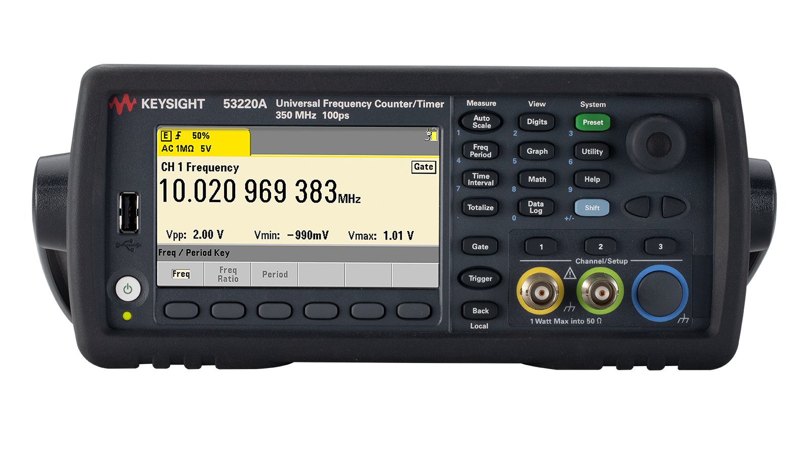
53220A 频率计 350MHz 详细指标
High-resolution time and frequency analysis
Input Characteristics (Nom) 53210A 53220A
53230A
Standard (DC - 350 MHz) Ch 1 Ch 1 & Ch
2
Optional (6 or 15 GHz) Ch 2 Ch
3
DC coupled DC (1 mHz) to 350 MHz (2.8 ns to 1000 sec)
AC coupled, 50 Ω1 or 1 MΩ
10 Hz - 350 MHz
Connector Front panel BNC(f). Option
201 adds parallel rear panel
BNC(f) inputs2
Input impedance (typ) Selectable 1 MΩ ± 1.5% or 50 Ω ± 1.5% ||
<25 pF
Input filter Selectable
100 kHz cut-off frequency low pass
10 Hz (AC coupling) cut-off frequency high pass filter
Input range
±5 V (±50 V) full scale ranges
Sensitivity3,4 (typ) DC - 100 MHz
20 mVpk
Noise3 500 µVrms (max)
350 µVrms (typ)
Threshold levels
±5 V (±50 V) in 2.5 mV (25 mV) steps
Noise reject4 Selectable On/ Off
Slope Selectable Positive or Negative
Auto-scale Acquires signal for current measurement channel, selects range (5 V or 50 V), sets auto-level
50%
Occurs once for each INIT or after a timeout
Measures signal Vpp and sets Trigger level to 50%
Off: Selectable user set level (Volts)
Minimum signal frequency for auto level User selectable (Slow (50 Hz), Fast (10 kHz))
Minimum signal for auto level
300 mVpp
Maximum Input 50 Ω damage level 1 W 50 Ω protection threshold Will not activate below 7.5 Vpk
50 Ω internal termination auto-protects by switching to 1 M Ω
1 M Ω damage level
DC - 5 kHz
350 Vpk (AC + DC)
5 kHz - 100 kHz: Derate linearly to 10 Vpk (AC + DC)
>100 kHz
10 Vpk (AC + DC)
Optional Microwave Inputs (Nom)
Option 106
100 MHz - 6 GHz
Option 115
300 MHz - 15 GHz
连接器前面板面板 precision 类型-N(f)
Option
203 moves the input connector to a rear panel SMA(f)
Input impedance (typ) 50 Ω ± 1.5% (SWR <
2.5)
Input Characteristics (Nom) 53210A 53220A
53230A
Option
106 Autoranged to +19 dBm max. (2 Vrms)
Option
115 Autoranged to +13 dBm max. (1.0 Vrms)
Sensitivity (typ)5
6 GHz (Opt 106)
-27 dBm (10 mVrms)
Level range Auto-ranged for optimum sensitivity and bandwidth
AM tolerance6
50% modulation depth
条件:1. AC coupling occurs after 50 Ω termination.
2. When ordered with optional rear terminals, the standard/baseband channel inputs are active on both the front and rear
terminals with rear terminals installed is not specified. 3. Multiply value(s) by 10 for the 50 V range. 4. Stated specification assumes Noise Reject OFF. Noise Reject ON doubles the sensitivity minimum voltage levels. 5. Assumes sine wave.
6. CW only. Assumes AM Rate > 10/gate. For Option 106, spec applies for input powers > - 20 dBm; use a tolerance of 15%
modulation depth for frequencies less than 900 MHz. For Option 115, spec applies for input powers > - 10 dBm.
Damage level 6 GHz (Opt 106): >
+27 dBm (5 Vrms)
15 GHz (Opt 115): >
+19 dBm (2 Vrms)
of the universal counter though the specifications provided only apply to the rear terminals. Performance for the front
Channels Ch 1 or optional Ch 2 Ch 1, Ch 2 or optional Ch
3
Digits/s 10 digits/s 12 digits/s
12 digits/s
Maximum display Resolution1 12 digits 15 digits
15 digits
Measurement technique Reciprocal Reciprocal and resolution enhanced
Gate time2
1 ms to 1000 s in
10 µs steps
100 µs to 1000 s in
10 µs steps
1 µs to 1000 s in
1 µs steps
Advanced gating3 N/A Start delay (time or events) and stop hold-off
Range9 DC (1 mHz) to 350 MHz (2.8 ns to 1000 s)
Microwave input (optional) Option
106 - 100 MHz to 6 GHz (166 ps to 10 ns)
Option
115 - 300 MHz to 15 GHz (66 ps to 3.3 ns)
Frequency Ratio4
Range
1015 Displayable range
Timestamp/Modulation Domain
Sample rate5 N/A N/A 1 MSa/s
800 kSa/s
#Edges/timestamp N/A N/A Auto-acquired per acquisition
Acquisition length N/A N/A up to 1 MSa or
100,000 s (max)
Time Interval (Single-shot) Measurements11
Single-shot time resolution N/A 100 ps
20 ps
Start delay (time or events) and stop hold-off (time or events)
Level N/A Independent start, stop slopes
Channel-to-channel time skew (typ) N/A 100 ps
50 ps
Range9 N/A
-1 ns to 100,000 s (nom)
-0.5 ns to 100,000 s (min)
Range N/A
2 ns to 100,000 s (min)
Minimum edge repetition rate N/A
6 ns
Level & slope N/A Auto-level or user selectable 53210A 53220A
53230A
Range6 N/A
-180.000º to 360.000º
Range9 N/A
0 to 1015 events
Gating N/A Continuous, timed, or external gate input
Voltage level - standard input channels
±5.1 Vpk with 2.5 mV resolution or ±51 Vpk with 25 mV resolution
Microwave power level (microwave channel option) 0 to 4 relative signal power 53210A 53220A 53230A 6 GHz (Option 106) 15 GHz (Option
115)
Pulse/Burst Frequency and Pulse Envelope Detector
12
Carrier frequency, carrier period, pulse repetition interval (PRI), pulse repetition frequency (PRF), positive and negative width
Pulse/burst width for carrier frequency measurements10 N/A N/A
> 200 ns
> 400 ns
Minimum pulse/burst width for envelope measurements N/A N/A > 50 ns >
100 ns
Acquisition N/A N/A Auto, Manual7
PRF, PRI range N/A N/A 1 Hz – 10 MHz
1 Hz - 5 MHz
Pulse detector response time (typ)8 N/A N/A 15 ns rise/fall
40 ns rise/fall
Pulse width accuracy N/A N/A
20 ns + (2*carrier
Power ratio (typ) N/A N/A >
15 dB
Power range and sensitivity (sinusoidal) (typ) N/A N/A
+13 dBm (1 Vrms) to
-13 dBm (50 mVrms)
mVrms) to -6 dBm (115
(630 mVrms) to -8
dBm (90 mVrms)
mVrms) to -6 dBm (115
Single-Period, 脉冲-Width, 上升时间, 下降时间
Minimum edge repetition rate N/A
6 ns
条件:Level & slope N/A Auto-level or user selectable 1. Maximum display resolution for frequency and period. Totalize display resolution is 15 digits, time interval based measurements are 12 digits. 2. Continuous, gap -free measurements limits the gate time setting to 10 µs to 1000 s in 10 µs steps.
3. Refer to the gate characteristics section for more details on advanced gate capabilities.
4. Measurements on each input channel are performed simultaneously using one gate interval. The actual measurement
gate interval on each channel will be synchronous with edges of each input signal.
5. Maximum sample rate. Actual sample rate will be limited by the input signal edge rate for signals slower than the
timestamp rates. 6. Assumes two frequencies are identical, only shifted in phase. 7. Manual control of gate width and gate delay are allowed only for wide pulsed mode. 8. For pulsed signals > - 7 dBm (100 mVrms) while gated on.
9. For totalize, time interval and frequency measurements, you may get measurement readings beyond the range stated,
but the accuracy of those readings is not specified. 10 . Applies when burst width * Carrier Freq > 80. 11 . Specifications apply if measurement channels are in 5 V range, DC coupled, 50 Ω terminated and at fixed level for: time interval single and dual channel, pulse width, duty, phase, single period and rise/fall time measurements.
12. Microwave pulse/burst measurement descriptions:
Range N/A .000001 to .999999 or 0.0001% to 99.9999%
selected sample rate. Maximum timestamp rate offers minimal FM tolerance. If high FM tolerance is required, use lower
Gate time (step size) 1 1 ms - 1000 s (10 µs) 100 µs - 1000 s (10 µs)
1 µs - 1000 s (1 µs)
Source N/A Internal or external, Ch 1/Ch
2
Slope N/A Positive or negative
Delay time1 N/A
0 s to 10 s in 10 ns steps
Delay events (edges) N/A
0 to 108 for signals up to 100 MHz
Advanced: gate stop hold-off
Source N/A Internal or external, Ch 1/Ch
2
Slope N/A Positive or negative
Hold-off time1 N/A Hold-off Time settable from 60 ns to 1000 s
Hold-off events (edges) N/A
0 to 108 (minimum width (positive or negative)
> 60 ns)
Selectable as 外部 gate 输入或 gate 输出信号
Impedance
1 kΩ when selected as external gate input
Slope Selectable positive or negative
Gate to gate timing
3 µs gate end to next gate start
Damage level < -5 V, >
+10 V
Selectable as 外部 gate 输入或 gate 输出信号
Impedance
50 Ω when selected for gate output
Slope Selectable positive or negative
Damage level < -5 V, >
+10 V
Trigger and Time-based Characteristics (Nom) 53210A 53220A
53230A
Trigger count
1 to 1,000,000
Trigger delay
0 s to 3600 s in 1 µs steps
Samples/trigger
1 to 1,000,000
Slope Selectable positive or negative
Pulse width >
40 ns min
Latency2 Frequency, period: 1 µs +
3 periods
time interval, totalize
100 ns
External trigger rate 300/s max 1 k/s max
10 k/s max
Damage level < -5 V, >
+10 V
条件:Lock range ±1 ppm (±0.1 ppm for Option 010 U-OCXO timebase)
Level (typ)
100 mVrms to 2.5 Vrms
Lock frequencies 10 MHz, 5 MHz
1 MHz
条件:1. Continuous, gap -free measurements limits the Gate Time setting to 10 µs to 1000 s in 10 µs steps.
2. Latency does not include delays due to auto -leveling.
Impedance 50 Ω
± 5% at 10 MHz
Level 0.5 Vrms into a
50 Ω load
(Nom) 53210A 53220A
53230A
Selectable 10 (slow), 100 (medium)
1,000 (fast) reading moving average
Selectable filter reset .1% /1000 ppm (fast), .03%/300 ppm (medium), .01%/100 ppm
(slow) change from average
Scaling mX-b or m(1/X)-b
User settable b (reference) value
最大, 最小, 峰值-to-Peak, count
Mean, standard deviation, Allan deviation2,
最大, 最小, 峰值-to-Peak, count
条件:Limit test 3 Displays PASS/ FAIL message based on user defined Hi/ Lo limit values.
Operation Individual and simultaneous operation of smoothing, scaling, statistics, and limit test
Selectable bin and block size
Limit test Measurement result, tuning bar-graph, and PASS/FAIL message
Markers Available to read values from trend & histogram displays
Data log Guided setup of # of readings/counts; automatically saves acquisition results to non-volatile memory
Instrument state Save & recall user-definable instrument setups
Power-off Automatically saved
Power-on Selectable power-on to reset (Factory), power-off state or user state
Volatile reading memory
1 M readings (16 MBytes)
Non-volatile internal memory
75 Mbytes (up to 5 M readings)
USB file 系统前面板-面板连接器 · USB 存储 device
Capability Store/recall user preferences and instrument states, reading memory, and bit map
Speed Characteristics4 (meas)
Measurement/IO timeout (nom) no timeout or 10 ms to 2000 s, in 1 ms steps
Auto-level speed Slow mode (50 Hz)
350 ms (typ)
Fast mode (10 kHz)
10 ms (typ)
Configure-change speed Frequency, Period, Range, Level
50 ms (typ)
Single Measurement Throughput5: Readings/s
(Time to take single measurement and transfer from volatile reading memory over I/O bus)
Typical (Avg. using READ?)
Optimized (Avg. using *TRG;DATA:REM?
1, WAIT):
Block Reading Throughput5: Readings/s (Example uses
50,000 readings)
(Time to take blocks of measurements and transfer from volatile reading memory over I/O bus)
Typical (Avg. using READ?)
LAN (sockets) 300 990
9700
Optimized (Avg. using *TRG;DATA:REM?
1, WAIT):
LAN (VXI-11) 300 990
34700
LAN (sockets) 300 990
55800
Maximum Measurement Speed to Internal Non-Volatile Memory6: (Readings/s)
Timestamp N/A N/A
1,000,000
Frequency, period, totalize
300
1000
75,000
Time interval, rise/fall, width, burst width N/A
90,000
条件:1. These Math operations do not apply for Continuous Totalize or Timestamp measurements.
2. Allan Deviation is only calculated for Frequency and Period measurements. Allan Deviation calculation is
3. Limit Test only displays on instrument front panel. No hardware output signal is available.
4. Operating speeds are for a direct connection to a >2.5 GHz dual core CPU running Windows XP Pro SP3 or better
5. Throughput data based on gate time. Typical reading throughput assumes ASCII format, Auto level OFF with
(DISP OFF), and set fastest gate time availab le. 6. Maximum 53230A rates represent >= 20 MHz input signals with min gate times, no delays or holdoffs.
LAN (sockets)
600,000 readings/sec
LAN (VXI-11)
150,000 readings/sec
available on both 53220A and 53230A, it is only gap free on
53230A.
with 4 GB RAM and a
10/100/1000 LAN interface.
READ? SCPI command. For improved reading throughput you should also consider setting (FORM:DATA REAL,64),
Measurement rates for the 53210A & 53220A are limited by min gate time. Actual meas rates are limited by the
repetition rate of the input being measured
General Characteristics (nom) 53210A 53220A
53230A
Display 4.3" Color TFT WQVGA (480 x
272), LED backlight
User interface and help languages English, German, French, Japanese, Simplified Chinese, Korean
USB flash drive FAT, FAT32
SCPI
532xx Series and 53131A/53132A/53181A Series compatibility mode
LXI-C 1.3 10/ 100/
1000 LAN (LAN Sockets and VXI-11 protocol)
USB 2.0 device port USB
2.0 (USB-TMC488 protocol)
GPIB interface GPIB (IEEE-488.1, IEEE-488.2 protocol)
Bench dimensions 261.1 mm W x 103.8 mm H x
303.2 mm D
Rack mount dimensions 212.8 mm W x 88.3 mm H x 272.3 mm D (2U x
1/2 width)
Weight
3.1 kg (6.9 lbs.) fully optioned
Storage temperature - 30 °C to +70 °C
Operating environment EN61010, pollution degree
2; indoor locations
Operating temperature
0 °C to +55 °C
Operating humidity
5% to 80% RH, non-condensing
Operating altitude Up to 3000 meters or 10,000 ft
Safety & EMC Refer to Declaration of Conformity for the latest revisions of regulatory
Acoustic noise (nom) SPL
35 dB(A)
Voltage 100V - 240V ± 10%, 50-60 Hz ±5%100 V - 120 V, 400 Hz
±10%
Power consumption
90 VA max when powered on
6 VA max when powered off/standby
Storage temperature limits
-10 °C to 60 °C
Operating time (typ) 3 hours when operated below
+35 °C
Standby time - OCXO powered (typ)
24 hours
条件:Figure 3. Dimensions apply to all three models: 53210A, 53220A, 53230A.
Cables Power line cord, 2 m USB
2.0
Timebase Uncertainty = (Aging + Temperature + Calibration Uncertainty)
条件:1. All Timebase Aging Errors apply only after an initial 30 -days of continuous powered operation and for a constant altitude
±100 m. After the first 1 -year of operation, use ½ x (30 -day and 1 -year) aging rates shown.
2. Additional temperature error is included in the time base uncertainty equation if the temperature of the operating
environment is outside the TCAL ± 5 °C (calibration temperature) range. The error is applied in its entirety, not per °C.
3. Initial factory calibration error applies to the original instrument calibration upon receipt from the factory. This error is
6. Retrace error may occur whenever the instrument line- power is removed. Retrace error is the residual timebase shift
that remains 72 -hours after powering -on an instrument that has experienced a full power -cycle of the timebase.
Additional frequency shift er rors may occur for instrument exposure to severe impact shocks > 50 g.
24-hour, TCAL ±1 °C
± 0.3 ppb (typ)
30-day, TCAL ±5 °C ± 0.2 ppm (typ)
± 10 ppb
1-year, TCAL ±5 °C ± 1 ppm
± 50 ppb
2-year, TCAL ±5 °C ± 0.5 ppm
± 25 ppb
0 °C to TCAL - 5 °C and TCAL + 5 °C to 55 °C ± 1 ppm
± 5 ppb
Initial factory calibration (typ) ± 0.5 ppm
± 50 ppb
Settability error ± 0.1 ppb
± 0.01 ppb
Supplemental Characteristics (Typ) 5-min. warm-up error 4 ± 1 ppm ± 10 ppb 72-hour retrace error 5 < 50 ppb <
2 ppb
Allan deviation τ = 1s 1 ppb
0.01 ppb
applied until the first re -calibration occurs after shipment. Settability error is the minimum adjustment increment
(resolution) achievable during electronic adjustment (calibration) of the instrument. It is added to the uncertainty of your
calibration source. 4. Warm -up error applies when the instrument is powered on in a stable operating environment. 5. When moved between different operating environments add the Temperature error during the initial
30 -minutes of powered operation
Figure
4. Front/rear view of 53230A
条件:measurement results for up to a maximum of approximately 13-digits or 100 fs.
The RSS of all random or Type-A measurement errors expressed as the total RMS or 1-σ
measurement uncertainty. Random uncertainty will reduce as
1/√N when averaging N
条件:instrument setup by performing relative measurements to eliminate the systematic components.
The 95% confidence residual constant or Type-B measurement uncertainty relative to an external
calibration reference. Generally, systematic uncertainties can be minimized or removed for a fixed
条件:The 95% confidence systematic uncertainty contribution from the selected timebase reference.
reference substitute, the specified uncertainty for your external frequency reference.
Use the appropriate uncertainty for the installed timebase or when using an external frequency
Basic accuracy
1 = ± [(k * Random Uncertainty) + Systematic Uncertainty + Timebase Uncertainty]
Function
1-σ Random Uncertainty Systematic Uncertainty Timebase
Uncertainty2
Period (parts error)
1.4* (TSS2 + TE2)1/2
If RE ≥ 2: 10 ps / gate (max)
2 ps / gate (typ)4
If RE < 2 or REC mode (RE = 1)
100 ps / gate •
Period (parts error)
1.4* (TSS2 + TE2)1/2
If RE ≥ 2: 10 ps / gate (max)
2 ps / gate (typ)4
If RE < 2
100 ps / gate •
Frequency Ratio A/B (typ) 5 (parts error)
1.4* Random Uncertainty of the worst case Freq input
Single Period (parts error)17 1.4* (TSS2 + TE2)
1/2
Time Interval (TI)17,
Width17, or
(parts error) 1.4* (TSS2 + TE2)
1/2
Offset (typ) = TLTE + skew + Taccuracy
•
(fraction of cycle error) 2* (TSS 2 + TE2) 1/2 * Frequency (TLTE +
2*Taccuracy)*Frequency
(Degrees error) 2* (TSS 2 + TE2)
1/2 * Frequency
* 360º (TLTE+skew+2*Taccuracy)*Frequency*360º
Totalize11 (counts error)
± 1 count11
5 V range
DC, 100 Hz - 1 kHz: 0.15% of reading +
0.15%
of range 1 kHz - 1 MHz: 2% of reading + 1% of range 1 MHz - 200 MHz: 5% of reading +
1% of range
+ 0.3 * (Freq/250 MHz) * reading
6 GHz (Option 106): Pulse/Burst Measurements3
13
PRF, PRI (parts error) 14 If RE > 1
200 ps / (RE * gate)
200 ps
(Narrow Mode) (parts error)
100 ps
(Wide Mode) (parts error)
40 ps
RE * Burst Width • 15 GHz (Option 115): Pulse/Burst Measurements3
13
PRF, PRI (parts error) 14
1 ns
(Narrow Mode) (parts error)
100 ps
条件:Timebase 3. Uncertainty column. 4. Assumes Gaussian noise distribution and non -synchronous gate, non- gaussian noise will affect Systematic Error. Note all optional microwave channel specifications (continuous wave and pulse/burst) assume sine signal.
5. Typical is achieved with an average of 100 readings with 100 samples per trigger. Worst case is trigger and sample
6. Improved frequency ratio, duty and phase specifications are possible by making independent measurements. Minimum
Pulse Width for using stated linearity is 5 Neila Stewart. Pulse Widths of 2 -5 ns use linearity=400 ps.
7. Residual instrument Rise/ Fall Time 10% -90% 2.0 ns (typ). Applies to fixed level triggering. Threshold can still be set
measurements need to be based on absolute threshold levels. 8. Input signal slew rates and settling time have effects on offset. Offset is calibrated with rise times < 100 ps. 9. Constant Duty or Phase are required during the measurement interval. Duty and Phase are calculated based on two automated sequential measurements - period and width or TI A to B, respectively.
10. Duty is represented as a ratio (not as a percent).
11. Additional count errors need to be added for gated totalize error, latency or jitter. If gated, add gate accuracy term
(See Totalize measurements in the Measurement Characteristics section).
12. Volts pk error apply for signal levels between full range and 1/10th range. Spec applies to sine wave only. 50 V range
reading accuracy is 2% at DC -1 KHz, 5% 1 KHz - 1 MHz band. Accuracy above 200 MHz is not specified on both ranges.
13. For 6 GHz (Opt 106): Specifications apply to signals from ±13 dBm, operable to ±19 dBm. For 15 GHz (Opt 115):
Specifications apply to input powers as listed under “Pulse/burst frequency and pulse envelope detector measurement
14. Use the RE equation, but use the input PRF for FIN. Assume sharp envelope transition.
15. Applies when Burst Width * Carrier Freq > 80.
16. Specifications based on gate and width for automated detection. If in manual mode, delay and width selected will
unless a Trigger Count of 1 and a large Sample Count acquisition method are used.
17. Specifications apply if measurement channels are in 5 V range, DC coupled, 50Ω terminated and at fixed level. The
(Wide Mode) (parts error)
75 ps
RE * Burst Width • 1. Apply the appropriate errors detailed for each measuring function. 2. Use Timebase Uncertainty in Basic Accuracy calculations only for Measurement Functions that show the • symbol in the
count set to 1.
based on % of auto- level detected peaks, but since these peak levels may contain unknown variations, accurate
characteristics”, operable from +13 dBm to -8 dBm.
impact accuracy specification. For approximate accuracy for manual gate, use the RE calculation, but FIN is now
106
and use gate as burst width. For input signals where PRI < 250 μs, double the
1 -σ Random Uncertainty specification
following 最小值脉冲 width 要求 apply
Single-Period: < 250 MHz
50% Duty
Phase, Dual Channel Time Interval: < 160 MHz
50% Duty
Single Channel Time Interval Rise to Fall
条件:Definition of Measurement Error Sources and Terms used in Calculations 53210A 53220A 53230A
RE
1 use RE equation use RE equation
以上指标摘自厂家官方数据手册,完整定义、测试条件与保证值口径以手册为准。完整指标、测试条件与定义口径请见产品页「软件和手册 | 白皮书」栏目中的官方数据手册。
是德科技 | KEYSIGHT · onetest 仪器资源库



 客服








 粤公网安备44030902003758