

 客服




总线连接:PXI Express
模拟输入阻抗:50 欧姆
示波器最大带宽:250 MHz
电压输入通道数量:8
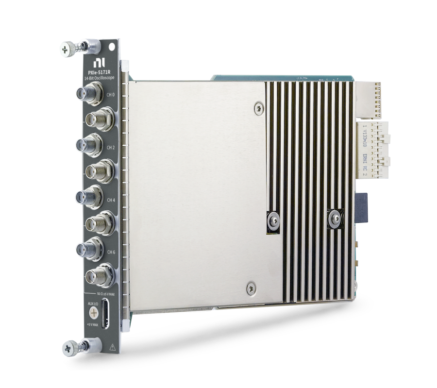
PXIe,250 MHz,8通道,14位,Kintex-7 410T FPGA可重配置PXI示波器
ONETEST 欢迎您
厂商登录 | 入驻
登录 | 注册 购物车 微信公众号厂商登录
总线连接:PXI Express
模拟输入阻抗:50 欧姆
示波器最大带宽:250 MHz
电压输入通道数量:8
PXIe,250 MHz,8通道,14位,Kintex-7 410T FPGA可重配置PXI示波器
以下指标取自 Teledyne 官方在线规格书,按原文档小节分组。
| CH 0—CH 7 | SMA connector |
| AUX I/O | MHDMR connector |
| 1 | GND |
| 2 | CLK IN |
| 3 | GND |
| 4 | GND |
| 5 | CLK OUT |
| 6 | GND |
| 7 | GND |
| 8 | AUX 0/PFI 0 |
| 9 | AUX 0/PFI 1 |
| 10 | GND |
| 11 | AUX 0/PFI 2 |
| 12 | AUX 0/PFI 3 |
| 13 | GND |
| 14 | AUX 0/PFI 4 |
| 15 | AUX 0/PFI 5 |
| 16 | AUX 0/PFI 6 |
| 17 | AUX 0/PFI 7 |
| 18 | +3.3 V |
| 19 | GND |
| 1 | PFI 0 |
| 2 | PFI 1 |
| 3 | PFI 2 |
| 4 | PFI 3 |
| 5 | NC |
| 6 | CLK IN |
| 7 | NC |
| 8 | CLK OUT |
| 9 | PFI 4 |
| 10 | PFI 5 |
| 11 | PFI 6 |
| 12 | PFI 7 |
| 13 | +3.3 V |
| 14 to 26 | GND |
| CLK IN | BNC female |
| CLK OUT | Used to export the reference clock |
| PFI 0 | Bidirectional PFI line |
| PFI 1 | Bidirectional PFI line |
| PFI 2 | Bidirectional PFI line |
| PFI 3 | Bidirectional PFI line |
| Number of channels | 8 (simultaneously sampled) |
| Input type | Referenced single-ended |
| Connectors | SMA |
| Input impedance | 50 Ω ± 1.5%, typical |
| Input coupling | AC, DC |
| Full-scale (FS) input range (Vpk-pk) | 0.2 V 0.4 V 1 V 2 V 5 V |
| Maximum input overload[2] | |Peaks| ≤ 5 V |
| Resolution | 14 bits |
| 0.2 V | ±(0.45 + 0.6 + 0.2) |
| 0.4 V | ±(0.45 + 0.24 + 0.2) |
| 1 V | ±(0.45 + 0.2 + 0.2) |
| 2 V | ±(0.40 + 0.2 + 0.2) |
| 5 V | ±(0.40 + 0.2 + 0.2) |
| DC accuracy sampling drift, full bandwidth (±% of |Reading| per MHz from 250 MHz)[3] 250 MHz − frequency 1 , 000 , 000 × DC accuracy sampling drift | ±0.03, nominal |
| AC amplitude accuracy Accuracy ±0.095 dB at 50 kHz, typical ±0.15 dB at 50 kHz, warranted Drift ±0.0013 dB per °C | Accuracy |
| Accuracy | ±0.095 dB at 50 kHz, typical ±0.15 dB at 50 kHz, warranted |
| Drift | ±0.0013 dB per °C |
| Conversion error rate[4] 250 MS/sec <1 × 10⁻¹⁰ 200 MS/sec <1 × 10-15 150 MS/sec <1 × 10-20 | 250 MS/sec |
| 250 MS/sec | <1 × 10⁻¹⁰ |
| 200 MS/sec | <1 × 10-15 |
| 150 MS/sec | <1 × 10-20 |
| Bandwidth-limiting filter | 100 MHz anti-alias filter |
| Bandwidth (-3 dB) Anti-alias filter 100 MHz Full bandwidth 0.2 Vpk-pk input range 260 MHz All other input ranges 270 MHz | Anti-alias filter |
| Anti-alias filter | 100 MHz |
| Full bandwidth 0.2 Vpk-pk input range 260 MHz All other input ranges 270 MHz | 0.2 Vpk-pk input range |
| 0.2 Vpk-pk input range | 260 MHz |
| All other input ranges | 270 MHz |
| <50 MHz | -0.5 dB to 0.5 dB |
| ≥50 MHz to <90 MHz | -1.0 dB to 0.5 dB |
| ≥90 MHz to <100 MHz | — |
| ≥100 MHz to <150 MHz | — |
| AC-coupling cutoff (-3 dB)[7] | 120 kHz |
| 0.2 V to 2 V | <10 MHz |
| ≥10 MHz to <30 MHz | -76.0 dBc |
| 5 V | <10 MHz |
| ≥10 MHz to <30 MHz | -73.0 dBc |
| <10 MHz | -77.0 |
| ≥10 MHz to <30 MHz | -73.0 |
| 0.2 V | <30 MHz |
| All other input ranges | <30 MHz |
| RMS noise Anti-alias filter enabled 0.017% of FS, typical Full bandwidth 0.2 Vpk-pk input range 0.037% of FS, typical 0.4 Vpk-pk input range 0.025% of FS, typical All other input ranges 0.024% of FS, typical | Anti-alias filter enabled |
| Anti-alias filter enabled | 0.017% of FS, typical |
| Full bandwidth 0.2 Vpk-pk input range 0.037% of FS, typical 0.4 Vpk-pk input range 0.025% of FS, typical All other input ranges 0.024% of FS, typical | 0.2 Vpk-pk input range |
| 0.2 Vpk-pk input range | 0.037% of FS, typical |
| 0.4 Vpk-pk input range | 0.025% of FS, typical |
| All other input ranges | 0.024% of FS, typical |
| 0.2 V | -159.2 dBm/Hz |
| 0.4 V | -153.7 dBm/Hz |
| 1 V | -145.7 dBm/Hz |
| 2 V | -139.7 dBm/Hz |
| 5 V | -131.7 dBm/Hz |
| 0.2 V | 149.2 dBFS/Hz |
| All other input ranges | 149.7 dBFS/Hz |
| 0.2 V | 3.5 nV/√Hz |
| 0.4 V | 6.5 nV/√Hz |
| 1 V | 16.4 nV/√Hz |
| 2 V | 32.7 nV/√Hz |
| 5 V | 81.8 nV/√Hz |
| Sources Internal Onboard clock (internal VCXO) External AUX I/O CLK IN (front panel MHDMR connector) PXIe_DStarA (backplane connector) | Internal |
| Internal | Onboard clock (internal VCXO) |
| External | AUX I/O CLK IN (front panel MHDMR connector) PXIe_DStarA (backplane connector) |
| Sample rate range, real-time[9] | 3.815 kS/s to 250 MS/s |
| Timebase frequency Internal 250 MHz External 150 MHz – 250 MHz[10] | Internal |
| Internal | 250 MHz |
| External | 150 MHz – 250 MHz[10] |
| Timebase accuracy Phase-locked to onboard clock ±25.0 ppm, warranted Phase-locked to external clock Equal to the external clock accuracy | Phase-locked to onboard clock |
| Phase-locked to onboard clock | ±25.0 ppm, warranted |
| Phase-locked to external clock | Equal to the external clock accuracy |
| Duty cycle tolerance | 45% to 55% |
| Sources Internal Onboard clock (internal VCXO) PXI_Clk10 (backplane connector) External (10 MHz) AUX I/O CLK IN (front panel MHDMR connector) | Internal |
| Internal | Onboard clock (internal VCXO) PXI_Clk10 (backplane connector) |
| External (10 MHz) | AUX I/O CLK IN (front panel MHDMR connector) |
| Duty cycle tolerance | 45% to 55% |
| Source | AUX I/O CLK IN (front panel MHDMR connector) |
| Impedance | 50 Ω |
| Coupling | AC |
| Input voltage range As a 250 MHz sine wave 1 dBm through 18 dBm As a fast slew rate input (square wave, Vpk-pk) 0.4 V to 5 V | As a 250 MHz sine wave |
| As a 250 MHz sine wave | 1 dBm through 18 dBm |
| As a fast slew rate input (square wave, Vpk-pk) | 0.4 V to 5 V |
| Maximum input overload As a 250 MHz sine wave 20 dBm As a fast slew rate input (square wave, Vpk-pk) 6 V | As a 250 MHz sine wave |
| As a 250 MHz sine wave | 20 dBm |
| As a fast slew rate input (square wave, Vpk-pk) | 6 V |
| Source | AUX I/O CLK IN (front panel MHDMR connector) |
| Impedance | 50 Ω |
| Coupling | AC |
| Frequency[11] | 10 MHz |
| Input voltage range As a 250 MHz sine wave 1 dBm through 18 dBm As a fast slew rate input (square wave, Vpk-pk) 6 V | As a 250 MHz sine wave |
| As a 250 MHz sine wave | 1 dBm through 18 dBm |
| As a fast slew rate input (square wave, Vpk-pk) | 6 V |
| Duty cycle tolerance | 45% to 55% |
| Source | PXI_Clk10 (backplane connector) |
| Destination | AUX I/O CLK OUT (front panel MHDMR connector) |
| Output impedance | 50 Ω |
| Logic type | 3.3 V LVCMOS |
| Maximum current drive | ±8 mA |
| Source | System timing slot |
| Destinations | Onboard clock (internal VCXO) FPGA |
| Source | PXI backplane |
| Destination | FPGA |
| Supported trigger | Reference (Stop) Trigger |
| Trigger types | Edge Window Hysteresis Digital Immediate Software |
| Trigger sources | CH 0 to CH 7 PFI <0..7> PXI_Trig <0..6> Software |
| Time resolution Analog triggers With interpolation Sample Clock period / 1024 Without interpolation Sample Clock period Digital triggers 2x Sample Clock period Approximate trigger delay difference between analog edge trigger and digital trigger source[12] 630 ns, nominal | Analog triggers With interpolation Sample Clock period / 1024 Without interpolation Sample Clock period |
| Analog triggers With interpolation Sample Clock period / 1024 Without interpolation Sample Clock period | With interpolation |
| With interpolation | Sample Clock period / 1024 |
| Without interpolation | Sample Clock period |
| Digital triggers | 2x Sample Clock period |
| Approximate trigger delay difference between analog edge trigger and digital trigger source[12] | 630 ns, nominal |
| Minimum dead time With interpolation 240 x Sample Clock period Without interpolation 130 x Sample Clock period | With interpolation |
| With interpolation | 240 x Sample Clock period |
| Without interpolation | 130 x Sample Clock period |
| Holdoff | From dead time to [(264 - 1) × Sample Clock timebase period] |
| Trigger delay | From 0 to [(251 - 1) × Sample Clock timebase period] |
| Analog trigger accuracy with input frequencies less than 90 MHz | 0.5% of full scale |
| Analog trigger jitter with input frequencies less than 90 MHz | 15 psrms |
| Minimum threshold duration[13] | Sample Clock period |
| Connector | AUX I/O |
| Direction | Bidirectional per channel |
| Direction control latency | 25 ns |
| As an Input (Trigger) Destination FPGA diagram Start Trigger (Acquisition Arm) Reference (Stop) Trigger Arm Reference Trigger Advance Trigger Input impedance 10 kΩ VIH 2 V VIL 0.8 V Maximum input overload 0 V to 3.3 V, 5 V tolerant Minimum pulse width 10 ns | Destination |
| Destination | FPGA diagram Start Trigger (Acquisition Arm) Reference (Stop) Trigger Arm Reference Trigger Advance Trigger |
| Input impedance | 10 kΩ |
| VIH | 2 V |
| VIL | 0.8 V |
| Maximum input overload | 0 V to 3.3 V, 5 V tolerant |
| Minimum pulse width | 10 ns |
| As an Output (Event) Sources FPGA diagram Ready for Start Start Trigger (Acquisition Arm) Ready for Reference Reference (Stop) Trigger End of Record Ready for Advance Advance Trigger Done (End of Acquisition) Output impedance 50 Ω Logic type 3.3 V CMOS Maximum current drive 12 mA Minimum pulse width 10 ns | Sources |
| Sources | FPGA diagram Ready for Start Start Trigger (Acquisition Arm) Ready for Reference Reference (Stop) Trigger End of Record Ready for Advance Advance Trigger Done (End of Acquisition) |
| Output impedance | 50 Ω |
| Logic type | 3.3 V CMOS |
| Maximum current drive | 12 mA |
| Minimum pulse width | 10 ns |
| Connector | AUX I/O/+3.3 V front panel connector |
| Voltage output | 3.3 V ± 10% |
| Maximum current drive | 200 mA |
| Output impedance | <1 Ω |
| Onboard memory size[14] | 1.5 GB |
| Minimum record length | 1 sample |
| Number of pretrigger samples | Zero up to (record length - 1) |
| Number of posttrigger samples | Zero up to record length |
| 1 | 10 |
| 1 | 1000 |
| 1 | 100,000 |
| 1 | 1M |
| 2 | 1 |
| 2 | 10 |
| 2 | 1000 |
| 2 | 100,000 |
| 2 | 1M |
| 4 | 1 |
| 4 | 10 |
| 4 | 1000 |
| 4 | 100,000 |
| 4 | 1M |
| 8 | 1 |
| 8 | 10 |
| 8 | 1000 |
| 8 | 100,000 |
| 8 | 1M |
官方规格书:https://www.ni.com/docs/en-US/bundle/pxie-5171-specs/page/specs.html
NI官方渠道
官方渠道(官网 / 热线 / 邮箱)
官方渠道(中国大陆)
• 官网 www.ni.com/zh-cn
• 在线选购 www.ni.com/zh-cn/shop.html
• 经销商查询
官网「查找经销商」 www.ni.com/zh-cn/shop/advisors.html
• 联系方式
NI 中文官网不公布中国区电话与邮箱,报价、技术支持、校准、维修一律通过官网在线表单提交(「联系我们」页)
全国办事处
公司总部
• NI(National Instruments)
• 地址
11500 N Mopac Expwy, Austin, TX 78759-3504, United States
• 母公司
Emerson(2023 年完成收购,NI 隶属艾默生测试与测量业务集团)
0条提问
X
提问
X
回答
发表口碑

AI问答




 粤公网安备44030902003758