是德科技 | KEYSIGHT
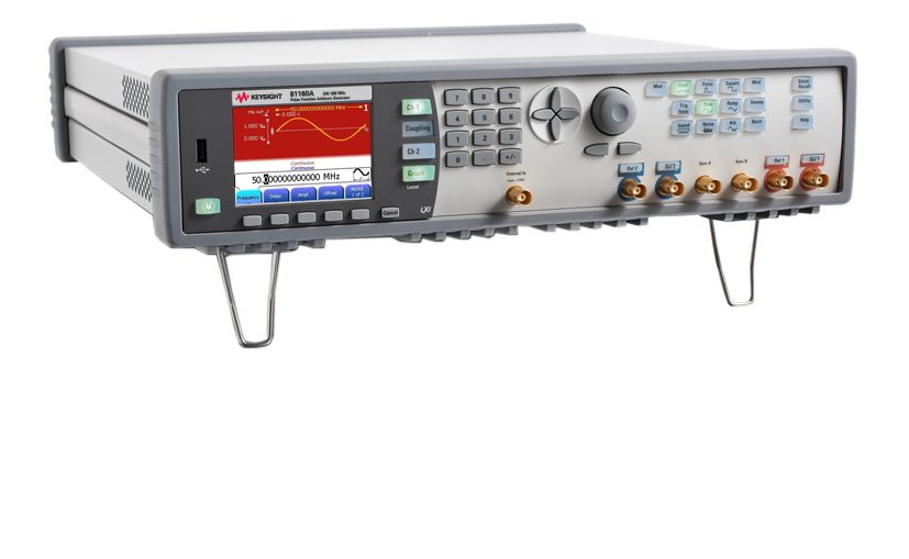
81150A 240MHz 波形发生器 详细指标
High-performance pulse generation with precise timing
High voltage amplifier 1 μHz to 120 MHz 1 μHz to 50 MHz
1 μHz to 330 MHz
Frequency resolution 1 μHz
1 μHz
Accuracy 4.1 ns to (period - 4.1 ns) typ. 10 ns to (period - 10 ns) 100 ps
6 digits
1.5 ns to (period - 1.5 ns) spec.
条件:1. Overshoot disappears for transitions times > 5 ns (high bandwidth amplifier) and > 15 ns (high voltage amplifier).
2. Overshoot disappears for transition times > 2 ns.
High voltage amplifier 2.5 ns to 1000 s (10% to 90%) 7.5 ns to 1000 s (10% to 90%) 100 ps
6 digits
-1000 ps to +500 ps
± 50 ppm
1.0 ns to 1000 s (10% to 90%)
Overshoot 2% typ.1
4% typ.2
High voltage amplifier 1 μHz to 240 MHz 1 μHz to 50 MHz
1 µHz to 500 MHz
Frequency resolution 1 μHz
1 μHz
Harmonic distortion (High bandwidth amplifier 50 Ω into 50 Ω)
1 μHz to 2 MHz
2 MHz to 10 MHz
10 MHz to 35 MHz
35 MHz to 70 MHz
70 MHz to 240 MHz
1 VPP
< -62 dBc spec.
< -57 dBc spec.
< -45 dBc spec.
< -35 dBc spec.
< -22 dBc spec.
3 VPP
< -62 dBc spec.
< -52 dBc spec.
< -40 dBc spec.
< -30 dBc spec.
< -17 dBc spec.
1 µHz to 2 MHz
2 MHz to 10 MHz
10 MHz to 50 MHz
50 MHz to 200 MHz
200 MHz to 500 MHz
1 VPP
< -65 dBc spec.
< -62 dBc spec.
< -50 dBc spec.
< -30 dBc spec.
< -22 dBc spec.
3 VPP
< -63 dBc spec.
< -53 dBc spec.
< -40 dBc spec.
< -27 dBc spec.
< -20 dBc spec.
Harmonic distortion (High voltage amplifier 50 Ω into 50 Ω)
1 μHz to 8 MHz
8 MHz to 50 MHz
10 VPP
< -40 dBc
< -25 dBc
Non-harmonic (spurious) distortion 1 μHz to 20 MHz
20 MHz to 200 MHz
200 MHz to 240 MHz
-60 dBc typ.
-55 dBc typ.
-50 dBc typ.
1 μHz to 1 MHz
1 MHz to 10 MHz
10 MHz to 280 MHz
280 MHz to 330 MHz
330 MHz to 500 MHz
-50 dBc typ.
-55 dBc typ.
-50 dBc typ.
-45 dBc typ.
-43 dBc typ.
SSB phase noise (10 kHz offset)
1 MHz
10 MHz
100 MHz
240 MHz
500 MHz
-119 dBc/Hz typ.
-115 dBc/Hz typ. —
-93 dBc/Hz typ. —
-115 dBc/Hz typ.
-115 dBc/Hz typ.
-110 dBc/Hz typ. —
-100 dBc/Hz typ.
High voltage amplifier 1 μHz to 120 MHz 1 μHz to 50 MHz
1 µHz to 330 MHz
Frequency resolution 1 μHz
1 μHz
High voltage amplifier (Freq/240 MHz) to 1 – (Freq/240 MHz) e.g. 60 MHz
25% to 75% (Freq/100 MHz) to 1 – (Freq/100 MHz)
(Freq/ 660 MHz) to 1 – (Freq/
660 MHz)
e.g. 3.3 MHz
0.5% to 99.5%
Transition time (10% to 90%)
High voltage amplifier 2.5 ns typ. fixed 6 ns typ. fixed
1.1 ns typ. fixed
Frequency range 1 μHz to 5 MHz
1 µHz to 20 MHz
Frequency resolution 1 μHz
1 μHz
Linearity < 0.1% (f < 10 kHz) < 0.1% (f <
10 kHz)
Symmetry 0.0% to 100%
0.0% to 100%
High voltage amplifier 120 MHz typ. 40 MHz typ.
160 MHz typ.
Amplitude distribution Selectable Gaussian, user defined Selectable Gaussian, user defined
Crest factor (peak/RMS) selectable 3.1, 4.8, 6.0, 7.0 typ. (Gaussian distribution) 3.1, 4.8, 6.0
7.0 typ. (Gaussian distribution)
Noise type Deterministic, triggerable Deterministic, triggerable
Repetition time ~ 26 days ~
20 days
六、Arbitrary Specifications
DAC sample rate 2 GSa/s1, fixed
2.5 GSa/s, fixed
Waveform length 2 to 512 k points 1-channel instrument
2 to 256 k points
2-channel instrument
2 to 128 k points
Wavelength vs. memory access rate
2 to 512 k points at memory access rate
1,000 MSa/s1
1-channel instrument, automatic selection:
128 k to 256 k points at memory access rate 625 MSa/s
2
64 k to 128 k points at memory access rate 1,250 MSa/s
3
2 to 64 k points at memory access rate
2,500 MSa/s
2-channel instrument, automatic selection:
64 k to 128 k points at memory access rate 625 MSa/s
2
32 to 64 k points at memory access rate 1,250 MSa/s
3
2 to 32 k points at memory access rate
2,500 MSa/s
DAC resolution 14 bits
14 bits
Frequency range 1 μHz to 120 MHz
1 µHz to 330 MHz
Frequency resolution 1 μHz
1 μHz
Transition time (10% to 90%)
High voltage amplifier 1.7 ns typ. 5 ns typ.
1.0 ns typ.
条件:1. One step linear interpolation between two memory samples. DAC clock rate is 2,000 MSa/s.
2. Three steps linear interpolation between two memory samples. DAC clock rate is 2,500 MSa/s.
3. One step linear interpolation between two memory samples. DAC clock rate is 2,500 MSa/s
High voltage amplifier 240 MHz typ. 80 MHz typ.
500 MHz typ.
PP jitter 1 ns typ. 400 ps typ. at memory sample rate
2,500 MSa/s
Advanced Modes Three advanced modes exist
– Modulation: selects the modulation type: AM, FM, PM, FSK, PWM
– Bursts: repeats selected waveform n times
条件:back-panel. In the two-channel instrument one channel can also modulate the other channel.
Input impedance Selectable 10 kΩ, 50 Ω nom. Selectable 10 kΩ, 50 Ω nom.
A modulation input (for AM, FM, PM, FSK, PWM) for each channel is provided on the
Modulation In 1/modulation In 2
Input range (full scale) Selectable ± 2.5 V or ± 5 V
± 2.5 V
Frequency range DC to 10 MHz DC to 10 MHz
连接器 BNC, back 面板 BNC, back 面板
Carrier waveforms Sine, square, ramp, arbitrary Sine, square, ramp, arbitrary
Internal modulation Sine, square, ramp (up, 50%, down), noise, arbitrary Sine, square, ramp (up
50%, down), noise, arbitrary
DC to 10 MHz
1 mHz to 50 MHz
DC to 10 MHz
Depth 0% to 120%
0% to 120%
Double-sideband suppressed carrier Selectable on/off Selectable on/off
Source Internal, external, channel Internal, external, channel
Carrier waveforms Sine, square, ramp, arbitrary Sine, square, ramp, arbitrary
Internal modulation Sine, square, ramp (up, 50%, down), noise, arbitrary Sine, square, ramp (up
50%, down), noise, arbitrary
DC to 10 MHz
1 mHz to 50 MHz
DC to 10 MHz
Deviation range 1 μHz to 240 MHz1
1 µHz to 500 MHz1
Source Internal, external, channel Internal, external, channel
Carrier waveforms Sine, square, ramp, arbitrary Sine, square, ramp, arbitrary
Internal modulation Sine, square, ramp (up, 50%, down), noise, arbitrary Sine, square, ramp (up
50%, down), noise, arbitrary
条件:1. Max frequency depends on selected waveform.
DC to 10 MHz
1 mHz to 50 MHz
DC to 10 MHz
Deviation range 0 to 360˚
0 to 360˚
Source Internal, external, channel Internal, external, channel
Carrier waveforms Sine, square, ramp, arbitrary Sine, square, ramp, arbitrary
Internal modulation 50% square
50% square
条件:1. Max frequency depends on selected waveform.
2. For export control: Effective switching time is 40 ns.
External 1 mHz to 50 MHz 1 mHz to 10 MHz
1 mHz to 50 MHz
1 mHz to 10 MHz
Frequency range 1 mHz to 240 MHz1, 2
1 mHz to 500 MHz1
Source Internal, external, channel Internal, external, channel
Internal modulation Sine, square, ramp (up, 50%, down), noise, arbitrary Sine, square, ramp (up
50%, down), noise, arbitrary
DC to 10 MHz
1 mHz to 50 MHz
DC to 10 MHz
Deviation range 0% to 100% of pulse width
0% to 100% of pulse width
Source Internal, external, channel Internal, external, channel
Sweep An independent frequency sweep is provided for each channel.
Waveforms Pulse, sine, square, ramp, triangle, arbitrary Pulse, sine, square, ramp, triangle, arbitrary
Direction Up or down Up or down
条件:Marker Frequency marker Frequency marker 3. Max frequency depends on selected waveform.
Sweep time 100 μs to 500 s
50 μs to 500 s
Start frequency/stop frequency 1 μs to 240 MHz3
1 μHz to 500 MHz1
Amplitude flatness (relative to 1 kHz
2 V PP)
— 1 μHz to 500 MHz
± 0.5 dB typ.
Trigger source External, internal, manual External, internal, manual
Burst An independent burst capability is provided for each channel.
Waveforms Pulse, sine, square, ramp, triangle, arbitrary Pulse, sine, square, ramp, triangle, arbitrary
Frequency 1 μHz to 120 MHz
1 µHz to 330 MHz
Modes Externally triggered, internally triggered, externally gated
Externally triggered, internally triggered, externally gated
# of waveforms in a burst 2 to 231 - 1 (~ 2 billion) 2 to 231 – 1 (~
2 billion)
Trigger period 16.7 ns to 9999 s
6.1 ns to 9999s
Start phase 4 –360 to +360˚
–360 to +360˚
条件:4. Available for all waveforms except pulse, square and ramp.
Trigger source External, internal, manual External, internal, manual
条件:Main outputs A selectable single-ended or differential output is provided for each channel on the front-panel.
2) typ.
High bandwidth amplifier 120 MHz pulse/240 MHz sine
330 MHz pulse/500 MHz sine
High voltage amplifier
50 MHz
Output type Single-ended or differential Single-ended or differential
Amplitude (50 Ω into
50 Ω)
High bandwidth amplifier 1 μHz to 120 MHz 120 MHz to 240 MHz
1 µHz to 330 MHz
330 MHz to 500 MHz
High voltage amplifier 1 μHz to 50 MHz 50 mVPP to 5 VPP
1 typ.
50 mVPP to 3VPP
1 typ.
100 mVPP to 10 VPP
1 typ.
50 mVPP to 5 VPP
1 typ.
50 mVPP to 3 VPP
1 typ.
Amplitude (50 Ω into open, 5 Ω into
50 Ω)
High bandwidth amplifier 1 μHz to 120 MHz 120 MHz to 240 MHz
1 µHz to 60 MHz
High voltage amplifier 1 μHz to 50 MHz 100 mVPP to 10 VPP 1 (to
9 VPP
100 mVPP to 5 VPP
1 typ.
200 mVPP to 20 VPP
1 typ.
100 mVPP to 10 VPP
1, 4 typ.
DC amplitude accuracy ± (1.5% of setting + 5 mV) ± (1.5% of setting +
5 mV)
Voltage window (50 Ω into
50 Ω)
–5 V to +5 V typ.
–10 V to +10 V typ.
–5 V to +5 V typ.
Voltage window (50 Ω into open, 5 Ω into
50 Ω)
条件:Connector BNC, front panel BNC, front panel 1. All amplitudes are single-ended amplitudes. Differential peak-peak amplitudes are twice the single-ended value. 2. 10 VPP for 50 Ω into open; 9 V PP for 5 Ω into 50 Ω. 3. Current of normal Out plus current of complement Out is limited to 440 mA per channel.
4. Only for 50 Ω into open.
–10 V to +10 V1 (-9 V to +9 V2) typ.
–20 V to +20 V typ.
–10 V to +10 V typ.4
DC offset accuracy ± 5 V voltage window ± 10 V voltage window
± 20 V voltage window
Resolution 1 mV, 4 digits 1 mV
4 digits
Output impedance Selectable 50 Ω / 5 Ω typ.
50 Ω nom.
Variable load impedance 0.3 Ω to 1 MΩ3
0.1 Ω to 1 MΩ
Protection Short-circuit protected, overload disables main output Short-circuit protected, overload disables main output
External reference output 81150A
81160A
Aging 10 MHz typ. ± 50 ppm ± 2 ppm
0 to 50 ºC
± 1 ppm per year
10 MHz spec.
± 10 ppm
± 1 ppm per year
Output level 1 V nom.
1 V nom.
Impedance 50 Ω nom., AC coupled
50 Ω nom., AC coupled
连接器 BNC, 后面板面板 BNC, 后面板面板
External reference input 81150A
81160A
Lock range 10 MHz ± 500 ppm 10 MHz
± 500 ppm typ.
Input level 200 mVpp to 5 Vpp
200 mVPP to 5 VPP typ.
Impedance 1 kΩ nom., AC coupled
1 kΩ nom., AC coupled
条件:A common external input is provided for both channels on the front panel.
The external input is used for external trigger or external gate modes.
Stabilty ± 2 ppm, 0 to 50 ºC ± 2 ppm
0 to 55 ºC
Aging ± 1 ppm per year
± 1 ppm per year
Frequency range DC to 120 MHz DC to 330 MHz
Input range –10 V to +10 V
–5 V to +5 V
Maximum input amplitude 10 VPP
10 VPP
Input sensitivity 200 mVPP Hysteresis low
200 mV PP
–10 V to 10 V
100 mV
–5 V to +5 V
100 mV
Impedance Selectable 10 kΩ/50 Ω, DC coupled Selectable
1 kΩ/50 Ω, DC coupled
Slope Selectable, rising/falling/both Selectable, rising/falling/both
Pulse width > 3.3 ns >
1.3 ns
Transition time <
100 ns
连接器 BNC, 前面板面板 BNC, 前面板面板
Frequency counter The frequency applied to external input is measured
Gate time, up to 330 MHz — 1 s, fix
条件:For 81150A, a separate trigger output is provided for each channel on the front-panel.
output has the frequency of the unmodulated carrier waveform, with a 50% duty cycle.
For FSK modulation, the trigger output has the same frequency as the data output.
In advanced mode internally/externally modulated (AM, FM, PM, PWM), the trigger
That is, it alternates between the two frequencies
If noise is selected , a trigger signal is generated when noise is restarted internally,
For all other modes of operation the trigger signal (TRIGGER OUT) marks the start of
each waveform period. 81150A Trigger Out 1/Trigger Out
81150A
Selectable TTL/ECL
0 V/2.5 V nom.
–0.85 V/–1.80 V nom.
Internally triggered, continuous
Externally triggered 50% duty cycle typ.
4 ns typ.
Transition time (20% to 80%)
2.0 ns typ.
Connector BNC, front panel 1. For output frequencies > 120 MHz, the trigger rate is ¼ of the output frequency. If a frequency sweep or a FSK frequency exceeds 120 MHz, the trigger rate is ¼ of the output frequency.
81150A Trigger Outputs
81150A Strobe Outputs A strobe output is provided for each channel on the front-panel of pulse generator
81150A. The strobe output signal has a different function, depending on the mode of
If no advanced mode is selected , the strobe output is a constant low.
In advanced mode internally/ externally triggered or gated burst , the strobe output
provides a signal indicating the duration of a burst. The rising edge of the strobe signal
is synchronized to the start of the first waveform period in a burst. The falling edge is
synchronized to the start of the last waveform period in the burst.
In advanced mode sweep with the frequency marker off , the strobe output is a pulse
with half the duration of the sweep. The strobe signal goes high at the beginning of the
In advanced mode sweep with the frequency marker on , the strobe output goes high at
the beginning of the sweep and goes low at the marker frequency.
In pattern mode (block mode = On) , the strobe output goes high at the beginning of
the pattern and goes low at the last bit of the pattern. Refer to the User Guide for more
In advanced mode internally/externally modulated (AM, FM, FSK, PM, PWM), the strobe
In pattern mode (block mode = On) , the logical strobe signal goes high at the beginning
of the pattern and goes low at the last bit of the pattern. Refer to the User Guide for
more details. 81150A Strobe Out 1/Strobe Out
81150A
Analog output level (modulator)
Selectable TTL/ECL
0 V/2.5 V nom.
–0.85 V/–1.80 V nom.
–2.0 V to 2.0 V (full scale)
Transition time (20% to 80%)
2.0 ns typ.
81160A Trigger and Strobe
条件:It is e.g. possible, that the logical trigger signal 1 functionality is routed simultaneously to Sync.
It is e.g. possible, that the logical trigger signal 1 functionality is routed simultaneously to Sync.
For the one-channel instrument as well as the two-channel instrument two high speed
outputs Sync Out A and Sync Out B are provided at the front panel. The Sync output
signals can be configured very flexibly by an internal switch matrix to output the logical
Trigger Out functionality or Strobe Out functionality according to the following switch
matrix. 1-channel instrument
81160A
Sync Out A source None, logical trigger signal 1, logical strobe signal
1
Sync Out B source None, logical trigger signal 1, logical strobe signal
1
2-channel instrument
81160A
Sync Out A source None, logical trigger signal 1, logical strobe signal
1
logical trigger signal 2, logical strobe signal
2
Sync Out B source None, logical trigger signal 1, logical strobe signal
1
logical trigger signal 2, logical strobe signal
2
Sync Out A/Sync Out B
81160A
Analog output level (modulator)
Selectable TTL, ECL
0 V/2.5 V nom.
–0.85 V/–1.80 V nom.
–2.0 V to 2.0 V (full scale),
Available, if routed to logical Strobe Out
Transition time
0.8 ns typ. (20%/80%)
条件:signal has the frequency of the unmodulated carrier waveform with 50% duty cycle.
The logical trigger signal is an internally generated signal that can be routed to the
BNC connector of Sync Out A or Sync Out B. For the two-channel instrument, the
logical trigger signal is generated for both, channel 1 and channel
2.
In advanced mode internally/externally modulated (AM, FM, PM, PWM), the logical trigger
For FSK modulation the logical trigger signal generates the same frequency as the data
output — it alternates between the two frequencies
If noise is selected , a trigger signal is generated when noise is restarted internally,
For all other modes of operation the logical trigger signal marks the start of each
Logical trigger signal 1/logical trigger signal
2
81160A
Internallly triggered, continuous
条件:1. For output frequencies > 330 MHz, the trigger rate is ½ of the output frequency. In pattern mode with
frequency exceeds 330 MHz, the trigger rate is ½ of the output frequency.
Externally triggered 50% duty cycle typ.
1.5 ns typ.
bit rate >
330 MBit/s, the trigger rate is ½ of the output frequency. If a frequency sweep or a FSK
条件:no advanced mode is selected, the logical strobe signal is constant low.
falling edge is synchronized to the start of the last waveform period in the burst.
The logical strobe signal is an internally generated signal that can be routed to the BNC
connector of Sync Out A or Sync Out B. For the two-channel instrument, the logical
strobe signal is generated for both, channel 1 and channel
2.
The logical strobe signal has a different function, depending on the mode of operation. If
In advanced mode internally/externally triggered or gated burst , the logical strobe
signal provides a signal indicating the duration of a burst. The rising edge of the logical
strobe signal is synchronized to the start of the first waveform period in a burst. The
In advanced mode sweep with the frequency marker off , the logical strobe signal is a
pulse with half of the duration of the sweep. The strobe signal goes high at the beginning
条件:high at the beginning of the sweep and goes low at the marker frequency.
In advanced mode sweep with the frequency marker on , the logical strobe signal goes
In advanced mode internally/externally modulated (AM, FM, FSK, PM, PWM), the logical
In pattern mode (block mode = On) , the logical strobe signal goes high at the beginning
of the pattern and goes low at the last bit of the pattern. Refer to the User Guide for
条件:channel addition is selected, channel 2 outputs the unchanged waveform of channel 2.
Digital Channel Addition If the instrument is equipped with two output channels, channel
2 can be added to
channel 1 internally. The maximum output voltage of channel
1 remains unchanged. If
八、Timing 特性外部 · timing 规格
Delay: External In to Main Out
2
Pattern mode: on Variable delay
1
Accuracy 366 ns typ. 350 ns typ.
406 ns typ.
Independent for Out 1, Out
2
0 s to 1000 s2
404 ns typ.
404 ns typ.
404 ns typ.
Independent for Out 1, Out
2
0 s to 1000 s2
条件:External In to Sync Out A, B 15 ps RMS typ. 15 ps RMS typ. 15 ps RMS typ.
1. Not available, if sweep or modulation is selected
2. Trigger period ≥ variable delay
3. External In amplitude > 500 mV. External In transition time < 10 ns. Valid for externally triggered
peak-peak jitter of 8 ns for the 81150A and 3.2 ns for the 81160A, measured with 50 Ω source
External In to Trigger Out
2
366 ns typ.
350 ns typ.
406 ns typ.
External In to Sync Out A, B 404 ns typ. 404 ns typ.
404 ns typ.
External In to Trigger Out
2
External In to Strobe Out
2
— 15 ps RMS typ. —
— 15 ps RMS typ.
pulse, square, sine, ramp, arb. Externally triggered noise or externally triggered sweep has
以上指标摘自厂家官方数据手册,完整定义、测试条件与保证值口径以手册为准。完整指标、测试条件与定义口径请见产品页「软件和手册 | 白皮书」栏目中的官方数据手册。
是德科技 | KEYSIGHT · onetest 仪器资源库


 客服










 粤公网安备44030902003758