是德科技 | KEYSIGHT
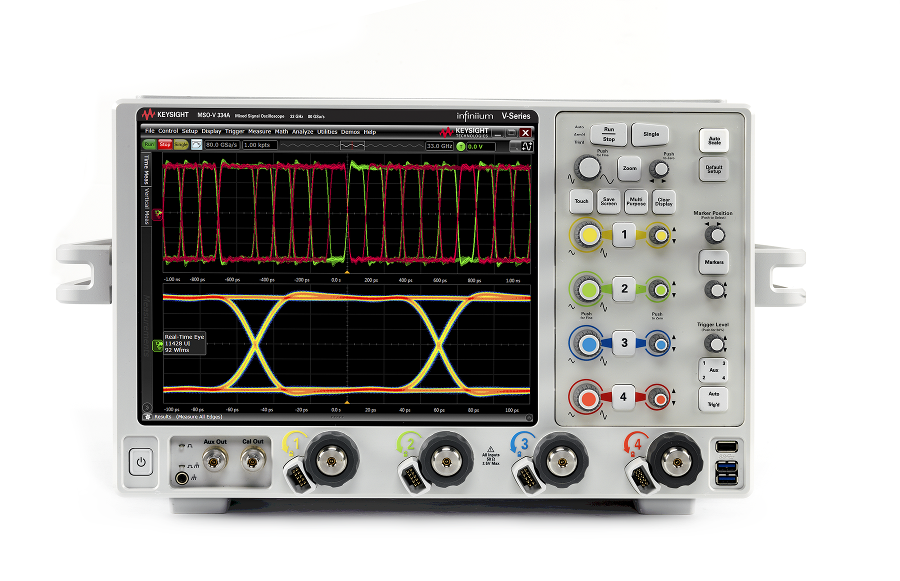
UXR系列MSOV334A 示波器 33GHz 详细指标
Benchtop Oscilloscopes
适用型号规格 V084A V134A V164A V204A V254A V334A
Input Channels DSO/DSA models - 4 analog
MSO models - 4 analog +
16 digital
Analog bandwidth(-3 dB)
2 channel 1 8 GHz 13 GHz 16 GHz 20 GHz 25 GHz
32 GHz
2 channel (typical) 8.4 GHz 13.6 GHz 16.8 GHz 21 GHz 26.2 GHz
33 GHz
4 channel 1 8 GHz 13 GHz 16 GHz 16 GHz 16 GHz
16 GHz
4 channel (typical) 8.4 GHz 13.6 GHz 16.8 GHz 16.8 GHz 16.8 GHz
16.8 GHz
Rise time/fall time 10 to 90% 5 55.0 ps 33.8 ps 27.5 ps 22.0 ps 17.6 ps 13.3 ps 20 to 80% 6 38.9 ps 23.9 ps 19.4 ps 15.6 ps 12.4 ps
9.4 ps
Input impedance 2 50 Ω
± 3%
Input sensitivity
1 mV/div to 1 V/div
Full scale hardware
60 mV to 8 V (oscilloscope only)
Sensitivity
60 mV to 1.2 V (oscilloscope with N7010A voltage termination adapter)
Vertical resolution 3, 4 8 bits, ≥
12 bits with high-resolution mode or averaging
Channel to channel Isolation (any two channels with equal V/div settings)
Channel-to-channel: 1-3, 1-4
2-3, and 2-4
Channel-to-channel
1-2 and 3-4
DC gain accuracy 1, 2, 3, 4 ± 2% of full scale at full resolution channel scale (± 2.5% for ≤
5 mV/div)
条件:1. Denotes warranted specifications, all others are typical. Specifications are valid after 30- minute warm up period and
2. Input impedance is valid when V/div scaling is adjusted to show all waveform vertical values within scope display.
3. Full scale is defined as eight vertical divisions. Magnification is used below 7.5 mV/div. Below 7.5 mV/div, full scale
is defined as 60 mV/div. The major scale settings are 1 mV/div, 2 mV/div, 5 mV/div, 10 mV/div, 20 mV/div, 50 mV/div,
4. Vertical resolution for 8 bits = 0.4% of full scale, for 12 bits = 0.024% of full scale.
5. Calculation based on Tr = 0.44/BW.
6. Calculation based on Tr = 0.31/BW.
Vertical sensitivity Available offset Available offset(with N7010A)
1 to 49 mV/div ± 0.4 V Additional
± 4 V
50 to 79 mV/div ± 0.7 V Additional
± 4 V
80 to 134 mV/div ± 1.2 V Additional
± 4 V
135 to 239 mV/div ± 2.2 V Additional
± 4 V
240 mV/div to 1 V/div ± 4.0 V Additional
± 4 V
Offset accuracy 1 ≤ 3.5 V: ± (2% of channel offset + 1% of full scale +
1 mV)
> 3.5 V: ± (2% of channel offset +
1% of full scale)
Dynamic range
± 4 div from center screen
DC voltage Dual cursor: ± [(DC gain accuracy) + (resolution)]
measurement accuracy Single cursor: ± [(DC gain accuracy) + (offset accuracy) + (resolution/2)]
± 5% from oscilloscope firmware calibration temperature.
100 mV/div, 200 mV/div
500 mV/div and 1V/div.
8 GHz
13 GHz
16 GHz
20 GHz
25 GHz
33 GHz
5 mV/div 0.21 mV 0.27 mV 0.31 mV 0.37 mV 0.45 mV
0.58 mV
10 mV/div 0.23 mV 0.28 mV 0.36 mV 0.42mV 0.49 mV
0.60 mV
20 mV/div 0.46 mV 0.57 mV 0.65 mV 0.74 mV 0.83 mV
1.04 mV
50 mV/div 1.04 mV 1.09 mV 1.32 mV 1.54 mV 1.73 mV
2.09 mV
100 mV/div 1.92 mV 2.30 mV 2.63 mV 3.02 mV 3.39 mV
3.98 mV
200 mV/div 4.39 mV 5.52 mV 6.14 mV 6.92 mV 8.16 mV
9.88 mV
500 mV/div 10.07 mV 12.42 mV 13.68 mV 15.05 mV 17.08 mV
20.25 mV
1V/div 18.47mV 21.36mV 26.12 mV 30.15 mV 34.36 mV
39.35 mV
RMS noise floor (with N7010A)
8 GHz
13 GHz
16 GHz
20 GHz
25 GHz
33 GHz
5 mV/div 0.28 mV 0.41 mV 0.44 mV 0.51 mV 0.65 mV
0.84 mV
10 mV/div 0.30 mV 0.42 mV 0.48 mV 0.57 mV 0.70 mV
0.86 mV
20 mV/div 0.54 mV 0.74 mV 0.84 mV 0.99 mV 1.20 mV
1.48 mV
50 mV/div 1.21 mV 1.64 mV 1.86 mV 2.18 mV 2.64 mV
3.21 mV
100 mV/div 2.42 mV 3.25 mV 3.68 mV 4.30 mV 5.16 mV
6.21 mV
200 mV/div 4.84 mV 6.48 mV 7.33 mV 8.53 mV 10.18 mV
12.18 mV
500 mV/div 12.16 mV 16.39 mV 18.64 mV 21.89 mV 26.42 mV
32.06 mV
1V/div 24.21mV 32.50 mV 36.80 mV 42.99 mV 51.55 mV
61.98 mV
ENOB (Effective number of
Bits) (Signal
80% of full Scale)
8 GHz
13 GHz
16 GHz
20 GHz
25 GHz
33 GHz
7 mV/div 5.9 5.7 5.5 5.4 5.1
5.0
10 mV/div 6.1 5.9 5.8 5.7 5.5
5.2
20 mV/div 6.3 6.1 6.0 5.8 5.6
5.4
50 mV/div 6.4 6.2 6.2 6.0 5.8
5.6
100 mV/div 6.6 6.4 6.2 6.0 5.8
5.6
Input Channels
16 digital channels
Threshold groupings Two individual threshold settings (one for channels 0 to 7 and one for channels
8 to 15)
Threshold selections TTL (1.4 V), CMOS (2.5 V), ECL (—1.3 V), PECL (3.7 V), custom
(
± 3.75 V in 10 mV increments)
Maximum input voltage
± 40 V peak CAT I
Threshold accuracy ± (100 mV +
3% of threshold setting)
Input dynamic range
± 10 V about threshold
Minimum input voltage swing
200 mV peak-to-peak
Input impedance (flying leads) 20 kΩ
± 2% (~0.7 pF) at probe tip
Analog bandwidth
3 GHz (depends on probing)
Characteristic Measured performance – All oscilloscope channels
Main timebase range
2 ps/div to 200 s/div
Main timebase delay range
200 s to -200 s real-time
Reference position Continuously adjustable across horizontal display range
Zoom timebase range
1 ps/div to current main timescale setting
Channel de-skew range ± 1 ms range
10 fs resolution
Time scale accuracy1,8 ± (0.1 ppm initial +
0.1 ppm/year aging)
Oscilloscope channel de-skew range ± 1 ms range
10 fs resolution
Intrinsic jitter6, acquired time
range/delta-time interval Internal reference External reference
< 1 μs (100 ns/div)
10 μs (1 μs/div)
100 μs (10 μs/div)
1 ms (100 μs/div)
100 fs rms
200 fs rms
500 fs rms
2 ps rms
100 fs rms
200 fs rms
200 fs rms
500 fs rms
Inter-channel intrinsic jitter3 <
100 fs rms
Inter-channel skew drift3,7 <
50 fs rms
Jitter measurement floor2 (sec rms)
+ (Intrinsic jitter)2
√2 ∗ ��Noise floor
+ (Intrinsic jitter)2
√3 ∗ ��Noise floor
+ (Intrinsic jitter)2
Inter-channel jitter2,3,5 (sec rms)
�� Time interval error (Edge Chan1)�
+ � Time interval error (Edge Chan2)�
+ �Inter 通道 intrinsic 抖动�
条件:calibration temp. 1. Sample rate at maximum. Noise and slew rate determined at fixed -voltage measurement threshold, near middle of signal.
3. Intra- channel = both edges on the same channel, Inter -channel = two edges on different channels. Time Interval Error(Edge1)
seco nd edge. 4. Reading is the displayed Delta Time Measurement Accuracy measurement value. Do not double the listed Time Scale Accuracy value in Delta Time Measurement Accuracy formula. 5. Scope channels and signal interconnect de- skewed prior to measurement.
6. External timebase reference values measured using a Wenzel 501 -04608A 10 MHz reference. Intrinsic jitter value depends on
acquisition time range for Time Interval Error formula and depends on delta -time between edges for all two- edge formulas.
7. Skew between channels caused by ± 5 °C temperature change.
8. Initial = immediately after factory or user calibration.
* Denotes warranted specification, all others are typical. Specs are valid after a 30 -minute warm -up period and
± 5 °C from
Displayed signal not vertically clipped. Slew rate of sine wave = (peak signal amplitude) ⦁
2 ⦁ π ⦁ f, slew rate of fast step
~= (10 to 90% rise time).
= time -interval error measurement floor of first edge, Time Interval Error(Edge2) = time -interval error measurement floor of
Delta-time measurement accuracy2,3,4,5
Intra-channel
256 averages
Inter-channel
256 averages
± �5 ∗ ��Time interval
error (Edge1)�
+ �Time interval error (Edge2)�
+ ��Time scale accuracy � ∗ �Delta time ��� ± �
5
16 ∗ �� TTTTTTTT TT iiiiTTii iiiiii
TT iiii eeii (EEEE EETT1)�
+ �TTTTTTTT TT iiiiTTii iiiiii
TT iiii eeii (EEEEEETT2)�
+ ��TTTTTTTT ssss iiiiTT iissss aaii iiss aa � ∗ �DDTTii iiii iiTTTTTT ��� ±
⎣
⎢
⎢
⎢
⎢
⎡5 ∗ �� Time interval
error (Edge1)�
+ �Time interval error (Edge2)�
+ �Inter 通道 intrinsic 抖动�
+ ��Time scale accuracy � ∗ �Delta time �� + �Inter channel skew drift � ⎦
⎥
⎥
⎥
⎥
⎣
⎢
⎢
⎢
⎢
⎡ 5
16 ∗ ��Time interval
error (Edge1)�
+ �Time interval error (Edge2)�
+ �Inter 通道 intrinsic 抖动�
条件:⎤ 2. Sample rate at maximum. Noise and slew rate determined at fixed -voltage measurement threshold, near middle of signal.
3. Intra- channel = both edges on the same channel, Inter -channel = two edges on different channels. Time
5. Scope channels and signal interconnect de- skewed prior to measurement.
+ ��Time scale accuracy � ∗ �Delta time �� + �Inter channel skew drift �
⎦
⎥
⎥
⎥
⎥
Displayed signal not vertically clipped. Slew rate of sine wave = (peak signal amplitude) ⦁
2 ⦁ π ⦁ f, slew rate of fast step
~= (10 to 90% rise time).
Interval Error(Edge1) = time -interval error measurement floor of first edge, Time Interval Error(Edge2) = time -
interval error measurement floor of second edge. 4. Reading is the displayed Delta Time Measurement Accuracy measurement value. Do not double the listed
Time Scale Accuracy value in Delta Time Measurement Accuracy formula.
Acquisition characteristic V084A
8 GHz
13 GHz
16 GHz
20 GHz
25 GHz
33 GHz
Maximum real-time sample rate 2 channels 80 GSa/s 80 GSa/s 80 GSa/s 80 GSa/s 80 GSa/s 80 GSa/s 4 channels 40 GSa/s 40 GSa/s 40 GSa/s 40 GSa/s 40 GSa/s
40 GSa/s
Memory depth per channel standard option 200 option
500
4 channels
100 Mpts
200 Mpts
500 Mpts
1 Gpts
2 Gpts
2 channels
100 Mpts
500 Mpts
1 Gpts
1 Gpts
2 Gpts
Maximum acquired time at highest real-time resolution standard option
200
40 GSa/s
2.5 ms
5 ms
12.5 ms
25 ms
50 ms
80 GSa/s
2.5 ms
5 ms
12.5 ms
12.5 ms
25 ms
Maximum waveform update rate >
400,000 waveforms per second (when in segmented memory mode)
Real-time Successive single shot acquisitions
Real-time with averaging Selectable from 2 to 65,534
Real-time with peak detect 80 GSa/s in 2-channel mode
40 GSa/s in 4-channel mode
Real-time with high resolution Real-time boxcar averaging reduces random noise and increases resolution
Equivalent time Resolution
338 fs
Gaussian magnitude, linear phase Slow filter roll off while maintaining linear phase
Roll mode Scrolls sequential waveform points across the display in a right-to-left rolling motion. Works at sample
rates up to 10 MSa/s with a maximum record length of 40 Mpts.
Segmented memory Captures bursting signals at max sample rate without consuming memory during periods of inactivity
Memory depth: 100 Mpts 200 Mpts 500 Mpts 1 Gpts
2 Gpts
Max # of segments: 16,384 32,768 65,536 131,072
131,072
Max time between triggers
562,950 seconds
Filters – Sin(x)/x On/off selectable FIR digital filter. Digital signal process adds points between acquired data points to
Maximum real-time sample rate 10 GSa/s with 16 channels
20 GSa/s with 8 channels
Maximum memory per channel Up to 1 Gpts
Minimum width glitch detection
50 ps
Trigger sources All channel inputs
1 auxiliary trigger input
Internal low
2.0 div p-p for 0 to 22 GHz
Internal high: 0.3 div p-p for 0 to 18 GHz, 1.0 div p-p for >
18 to 22 GHz
Edge trigger bandwidth >
20 GHz
Software (InfiniiScan) 250 ps
40 ps
Auxiliary ± 4 div from center screen or ± 4 V, whichever is smaller ± 5 V (into 50 Ω)
5 Vpp maximum input signal swing
Sweep modes Auto, triggered, single, segmented
条件:Trigger actions Specify an action to occur (and the frequency of the action) when a trigger conditions occurs.
Actions include email on trigger and execute "multipurpose" user setting.
Display jitter 2, 3, 4 (Trigger jitter)
230 fs rms
Trigger holdoff range
100 ns to 10 s
Trigger qualification (AND qualifier) Single and multiple channels may be logically qualified with any other trigger mode
Three stage trigger sequences including two-stage hardware (find event (A) and trigger event
(B)) and one-stage InfiniiScan software trigger. Supports all hardware trigger modes except
“edge then edge” and “video” and "Gbit serial." Supports “delay (by time)” and “reset (by time or
event)” between two hardware sequences. The minimum latency between “find event (A)” and
“trigger event (B)” is
3 ns.
条件:1. Denotes warranted specifications, all others are typical. Specifications are valid after a 30- minute warm -up period and ± 5 °C
from firmware calibration temperature. 2. Internal edge trigger mode with JitterFree correction. Value depends on scope settings and trigger signal characteristics, an d is equal to TIE value expressed in the formula above using the minimum Time Scale Accuracy value. 3. Value shown represents typical Display jitter for DSOV164A at 100 mV/div triggering on 500 mVpp 8 GHz sin wave signal.
4. Sample rate at maximum. Noise and slew rate determined at fixed -voltage trigger threshold, near middle of signal. Displayed
Threshold range (user-defined)
± 3.75 V in 10 mV increments
Threshold accuracy ± (100 mV +
3% of threshold setting)
Protocol triggering All MSO models come standard with protocol trigger for DDR, LPDDR, DDR2, LPDDR2, DDR3,
LPDDR3, DDR4, and LPDDR4
Edge (analog and digital) Triggers on a specified slope (rising, falling, or alternating between rising and falling) & voltage level on any
Edge transition (analog) Trigger on rising or falling edges that cross two voltage levels in > or < the amount of time specified. Edge
transition setting from 250 ps.
边沿 then 边沿 (时间)(analog 和数字)
The trigger is qualified by an edge. After a specified time-delay between
10 ns to 10 s, a rising or falling
边沿 then 边沿 (event)(analog 和数字)
条件:another rising or falling edge on any one selected input will generate the trigger.
The trigger is qualified by an edge. After a specified delay between
1 to 16,,000,000 rising or falling edges
Glitch (analog and digital)
条件:narrowest pulse and a polarity. Triggers on glitches as narrow as 125 ps.
Triggers on glitches narrower than the other pulses in your waveform by specifying a width less than your
Glitch range settings from 250 ps to <
10 s.
Trigger on a pulse that is wider or narrower than other pulses in waveform by specifying a pulse width & a
polarity. Triggers on pulse widths as narrow as 125 ps. Pulse width range settings
250 ps to 10 s. Trigger
point can be configured for “end of pulse” or “time out”
Runt (analog) Trigger on a pulse that crosses one threshold but fails to cross a second threshold before crossing the first
again. Can be time qualified with minimum setting of 250 ps.
Timeout (analog and digital)
条件:Level voltage (Unchanged Too Long). Timeout settings from 250 ps to 10 s.
Triggers the oscilloscope when the waveform has been at a higher voltage than the voltage specified by
the Level control for too long (High Too Long), when the waveform has been at a lower voltage than the
Level voltage for too long (Low Too Long), or when the waveform has taken too long to pass through the
Setup and hold (analog) Trigger on setup, hold or setup and hold violations in your circuit. Requires a clock and data signal on any
two inputs (except aux or line) channels as trigger sources. Setup and/or hold time must then be specified
条件:stays outside the range for too long or too short, or stays inside the range for too long or too short.
Specify a voltage range and then trigger when the waveform either exits this range, enters this range,
Range setting from 250 ps to 10 s.
• Triggers on bit patterns at rates from 480 Mb/s to 12.5 Gb/s
• Generic mode - Trigger up to 160-bit sequence of arbitrary NRZ data (high, low, don’t care)
• 8b/10b mode - Trigger up to 10 “K” and “D” code symbols. Alignment character is K28.5 (either
• PRBS errors mode - Count accumulated bits and errors, and trigger bit error for PRBS
15
23, and 31
条件:Protocol Trigger on certain packets or patterns in protocol-based data.
Triggers from negative sync composite video, field 1, field
2, or alternating fields for interlaced systems
any field, specified line or any line for interlaced or non-interlaced systems. Support NTSC, PAL-M
(525/60), PAL, SECAM (625/50), EDTV (480p/60), EDTV (576p/50), HDTV (720p/60), HDTV (720p/50),
HDTV (1080i/60), HDTV (1080i/50), HDTV (1080p/60), HDTV (1080p/50), HDTV (1080p/30), HDTV
(1080p/25), HDTV (1080p/24) and user-defined formats
Trigger modes – software (Requires D9020SCNA InfiniiScan event identification software)
Zone qualify Software triggers on the user-defined zones on screen. Zones can be specified as either “must intersect” or “must not
intersect.” Up to eight zones can be defined across multiple channels.
Software triggers on NRZ-encoded data up to 8.0 Gbps, up to 80-bit pattern. Support multiple clock data recovery
methods including constant frequency, 1st-order PLL, 2nd-order PLL, explicit clock, explicit 1st-order PLL, explicit
2nd-
order PLL, Fibre Channel, FlexRay receiver, FlexRay transmitter
条件:Non-monotonic edge Software triggers on the non-monotonic edge. The non-monotonic edge is specified by setting a hysteresis value.
again. Unlike hardware runt trigger, InfiniiScan runt trigger can be further qualified via a hysteresis value.
Software triggers on the results of the measurement values. For example, when the “pulse width” measurement is turned
on, InfiniiScan measurement software trigger triggers on a glitch as narrow as
40 ps. When the “time interval error (TIE)”
is measured, InfiniiScan can trigger on a specific TIE value.
Runt Software triggers on a pulse that crosses one threshold but fails to cross a second threshold before crossing the first
Oscilloscope measurements
Number of measurements Up to 40 simultaneous measurements (can be made on either main, zoom or gated region)
Measurement update rate >
50,000 measurement/sec (one measurement turned on)
> 250,000 measurement/sec/measurement (ten measurements turned on)
Displays the current, mean, minimum, maximum, range (max-min), standard deviation, number of
measurements value for the displayed automatic measurements. Also shows Fail Min and Fail Max when
Level qualification Any channels that are not involved in a measurement can be used to level-qualify all timing measurements
V peak-peak, V min, V max, V upper, V middle, V lower, V overshoot, V preshoot, V time, peak-peak
contrast, average, RMS, amplitude, base, top, overshoot, preshoot, crossing, pulse top, pulse base, pulse
Rise time, fall time, period, frequency, positive width, negative width, duty cycle, Tmin, Tmax, Tvolt,
channel-to-channel delta time, channel-to-channel phase, count pulses, burst width, burst period, burst
interval, setup time, hold time, edge-edge, edge time, slew rate
Time (digital) Period, frequency, positive width, negative width, duty cycle, delta time
Clock (analog) Period, frequency, duty cycle, phase, time interval error (TIE), cross-corelated TIE, N-period, period to
period, positive width to positive width, neg width to neg width, duty cycle to duty cycle
Data (analog) Setup time, hold time, unit interval, N Unit Interval, unit interval to unit interval, noise, data rate, pattern
length, CDR clock recovery rate, deemphasis, BER (cumulative), BER (per acq)
Mixed (analog) Area, slew rate
Frequency domain (analog) FFT frequency, FFT magnitude, FFT delta frequency, FFT delta magnitude, FFT channel power, FFT
power spectral density, FFT occupied bandwidth, peak detect mode
Eye-diagram (analog) Eye height, eye width, eye one level, eye zero level, eye jitter, eye skew, eye level, crossing percentage, Q
Jitter analysis measurements – Requires D9020JITA EZJIT complete analysis application
Clock Time interval error, N-period, period to period, positive width to positive width, neg width to neg width, duty
Data Time interval error, noise, unit interval, N Unit Interval, unit interval to unit interval, data rate, clock recovery
PAMn measurements – Requires D9020PAMA PAM4 analysis application
Level mean, level RMS, level skew, level thickness, eye height, eye width, eye skew, eye level, VEC, BER
(Cumulative), BER (Per Acq), SER (Cumulative), SER (Per Acq), clock recovery rate, pattern length, rise
time, fall time, and time interval error (TIE), composite histograms
Edge jitter measurements PAM-4
12 Edge Jitter, J3U, J4U J5U, Jrms, J6U, and EOJ
(PRBS9, PRBS13Q, PRBS31Q, PCIe Gen6 (52 symbols) and user defined pattern support up to PRBS23)
PAM formats PAM-3, PAM-4, PAM-6, PAM-8, grey coded, uncoded
Orientation Vertical (for timing and jitter measurements) or horizontal (noise and amplitude change) modes, regions
Mean, standard deviation, mean ± 1 2, and 3 sigma, median, mode, peak-to-peak, min, max, total hits
peak (area of most hits), X scale hits, X offset hits, full width at half maximum (FWHM), bin width
Allows pass/fail testing to user-defined or Keysight-supplied waveform templates. Automask lets you
create a mask template from a captured waveform and define a tolerance range in time/voltage or screen
divisions. Test modes (run until) include test forever, test to specified time or event limit, and stop on
Hardware accelerated math operations Differential and common mode
Absolute value, add, amplitude demodulation (radar envelope), average, bus chart, Butterworth1, common
mode, delay, differentiate, divide, envelope, FFT magnitude, FFT phase, FIR1, gating, high pass filter,
histogram, InfiniiSim2 (2 port, 4 port 1 src, 4 port CM, 4 port diff, 4 port src1
4 port src2), horizontal gating
integrate, invert, LFE1, low pass filter (4th-order Bessel Thompson filter), magnify / duplicate, max,
measurement trend, measurement log, min, multiply, pattern average, power, power efficiency, RT Eye1,
smoothing, SqrtSumOfSquare1, square, square root, subtract, versus (XY), versus (XYZ qualified) and
optional user defined function1
1 Requires MATLAB® software option
2 Requires D9020ASIA software option
Window modes Hanning, flattop, rectangular, Blackman-Harris, Hamming
Automatic measurements Measure menu access to all measurements, up to 40 measurements can be displayed simultaneously
Multipurpose Front-panel button activates up to ten pre-selected or up to ten user-defined automatic measurements
Drag-and-drop measurement toolbar
Measurement toolbar with common measurement icons that can be dragged and dropped onto the
Marker modes Manual markers, track waveform data, track measurements, track RF (on FFT math function waveforms)
Bookmarks and callouts Supports callouts for measurements and FFT peaks. Supports bookmarks for team collaboration
四、Platform Specifications
Computer system, peripherals and accessories
Operating system Microsoft Windows 10
64-bit or newer Microsoft Windows release
CPU Intel i5-3550S quad-core CPU at 3.00 GHz or higher performance CPU
PC system memory
16 GB DDR3 RAM or higher capacity/performance RAM
PC ports USB 2.0 hi-speed (host), USB 2.0 hi-speed (device), VGA, DisplayPort, USB 3.0 (host), USB
3.0 (device)
dual-monitor video output
10/100/1000 LAN, LXI LAN, GPIB (IEEE-488)
Drives (SSD) 500GB Enterprise grade internal SSD removable hard drive or higher capacity/performance SSD
Peripherals Optical USB mouse, compact USB keyboard supplied. All Infiniium models support any Windows-
Compressed internal format (*.wfm (200 Mpts)),
Comma-separated values (*.csv (2 Gpts)),
Tab-separated values (*.tsv (2 Gpts)),
Public binary format (.bin (500 Mpts)),
Y value files (*.txt (2 Gpts)), hierarchal data file (*.hf5 (2 Gpts)),
Composite setup and data file (*.osc (2 Gpts))
Digital Waveforms Hierarchal data file (*.hf5 (2 Gpts)),
Composite setup and data file (*.osc (2 Gpts))
Country-specific power cord, front cover, mini USB keyboard, USB optical mouse, and an ESD wrist strap
Five coax adapters (female-to-female)
条件:The 8 and 13 GHz models come standard with two N5442A precision BNC adapters.
• 8
13, and 16 GHz models come with 3.5 mm female-to-female adapters rated to 25 GHz (part
• All other models (20, 25
33 GHz) come with 3.5 mm female-to-female adapters rated to 35
GHz (part number
5061-5311)
Aux in External trigger input
50 Ω impedance
Aux out 100 MHz, square wave, PRBS 27-1, PRBS 215-1, PRBS 223-1, and PRBS
231-1
Cal out DC (± 2.4 V), 100 MHz, square wave, PRBS 27-1, PRBS 215-1, PRBS 223-1, and PRBS
231-1
External clock reference input to the hardware serial trigger
Peak-to-peak amplitude: 0.8 V to 3.6 V. Voltage range
-0.1V to 3.7V
Clock rise and fall time (10 to 90%)
1 ns or faster
Reference clock output Sub-rate clock output generated by the hardware serial trigger
Peak-to-peak amplitude into 50 Ω: 1 V, offset
0 V
Pattern generator1
Demo 码型输出从 hardware serial 触发
条件:1. Models with hardware serial trigger option
Peak-to-peak amplitude into 50 Ω: 400 mV, offset
400 mV
Timebase reference input1 Input frequency lock range: 10 MHz ±5 ppm
50 Ω impedance
Amplitude, sine wave input
178 mVpp to 1 Vpp
Timebase reference output1 Peak-to-peak amplitude into 50 Ω: 750 mV, offset
0 V when derived from the internal reference
Signal amplitude follows reference input when derived from external reference
Trig out Peak-to-peak amplitude into 50 Ω: 2.4 V, offset
0 V
Display
15.4-inch color XGA TFT-LCD with capacitive touch screen
Intensity grayscale
256-level intensity-graded display
Resolution XGA 1024 pixels horizontally x
768 pixels vertically
Annotation Up to 100 bookmarks can be inserted into the waveform window. Each can float or be tied to a specific
Grids Choose between 1-16 grids per waveform area
8-bit vertical resolution
Waveform areas Supports eight waveform areas plus chart mode for EZJIT, InfiniiSim, protocol, and PrecisionProbe
Waveform styles Connected dots, dots, infinite persistence, color graded infinite persistence. Includes up to 256 levels of
Temperature Operating
5 to +40 °C
Non-operating
–20 to +65 °C
Humidity Operating: Up to 95% relative humidity (non-condensing) at +40 °C
Non-operating: Up to 90% relative humidity at +65 °C
Altitude Operating: Up to 4,000 meters (12,000 feet
Non-operating: Up to 15,300 meters (50,000 feet)
Operating random vibration 5 to 500 Hz
10 minutes per axis,0.21 g(rms)
Non-operating random vibration 5 to 500 Hz, 10 minutes per axis, 2.0 g(rms); resonant search
5 to 500 Hz
Swept sine, 1 octave/minute sweep rate, (0.50 g)
5 minute
resonant dwell at 4 resonances per axis
Power 100 to 240 VAC at 50/60 Hz; input power
800 Watts
Weight Frame: 52.2 lbs. (23.7 kg); shipping
71.7 lbs. (32.5 kg)
Dimensions Height: 10.5 in (26.6 cm); width: 17.2 in (43.6 cm); depth
19.4 in (49.2 cm)
IEC 61010-1:2010/EN 61010-1
3rd Edition
CAN/CSA-C22.2 No.
61010-1-12
UL Std. No.
61010-1(3rd Edition)
条件:An attribute measured during development for purposes of communicating the expected performance.
This data is not warranted, does not include measurement uncertainty, and is measured at room
temperature (approximately
23°C).
条件:measured at room temperature (approximately 23°C).
The mean or average characteristic performance, or the value of an attribute that is determined by design
such as a connector type, physical dimension, or operating speed. This data is not warranted and is
条件:within the operating temperature range of 5 – 40°C and after a 30-minute warm up period.
The warranted performance of a calibrated instrument that has been stored for a minimum of 2 hours
The characteristic performance, which 80% or more of manufactured instruments will meet. This data is
not warranted, does not include measurement uncertainty, and is valid only at room temperature
条件:deembeding for frequency and phase characteristics of the individual hardware.
The operating frequency range is the frequency range of corrected signal spectral components by
The analog bandwidth describes the
3 dB bandwidth of the full opto-electronic input path without any
条件:assumed added Gaussian white noise (AWGN) according to =0.5*ERFC(1/(SQRT (2)* (EVM²+1))).
The sensitivity limit corresponds to the received signal power at the input interface for which a
32 GBaud
DP-QPSK exhibits an EVM of 32.5% or less. An EVM of 32.5% corresponds to a BER of 1E
-3 for
Effective Number of Bits (ENOB)
条件:Definition in accordance with IEEE 1057: “For an input sinewave of specified frequency and amplitude,
the rms NAD of the waveform recorder under test.” ENOB is determined by equation.
ENOB is the number of bits of an ideal waveform recorder for which the rms quantization error is equal to
Confidently Covered by Keysight Services
Prevent delays caused by technical questions, or system downtimes due to instrument maintenance and
repairs with Keysight Services. Keysight Services are here to support your test needs with expert
technical support, instrument repair and calibration, software support, training, alternative acquisition
program options, and more
A KeysightCare agreement provides dedicated, proactive support through a single point of contact for
instruments, software, and solutions. KeysightCare covers an extensive group of instruments, application
software, and solutions and ensures optimal uptime, faster response, faster access to experts, and faster
条件:Application Software Support. See the KeysightCare data sheet for details.
KeysightCare KeysightCare provides elevated support for Keysight instruments and software, with
access to technical support experts that respond within a specified time and ensure
committed repair and calibration turnaround times (TAT). KeysightCare offers
multiple service agreement tiers, including KeysightCare Assured, Enhanced, and
KeysightCare Assured KeysightCare Assured goes beyond basic warranty with repair services that include
committed TAT and unlimited access to technical experts
KeysightCare Enhanced KeysightCare Enhanced includes all the benefits of KeysightCare Assured plus
Keysight’s accurate and reliable calibration services, accelerated, and committed
All KeysightCare tiers include access to the Keysight Support Portal where you can
manage support and service resources related to your assets such as service
requests, and status, or browse the Knowledge Center
条件:Education Services developed by Keysight experts. Including Start-up Assistance.
Education Services Build confidence and gain new skills to make accurate measurements, with flexible
Alternative acquisition options
条件:instruments, software, and technical support you want for your test needs.
KeysightAccess Reduce budget challenges with a subscription service enabling you to get the
Keysight enables innovators to push the boundaries of engineering by quickly solving
design, emulation, and test challenges to create the best product experiences. Start your
This information is subject to change without notice. © Keysight Technologies
2018 – 2024
Published in USA, September 19, 2024 , 5992-
0425EN
Maximize your test system up-time by securing technical support, repair, and calibration services with
committed response and turnaround times.
1-year KeysightCare Assured is included in every new
instrument purchase Obtain multi-year KeysightCare upfront to eliminate the need for lengthy and tedious
paperwork and yearly requests for maintenance budget. Plus, you benefit from secured service for
3
or 5 years.
KeysightCare Enhanced* Includes Tech Support, Warranty and Calibration
R-55B-001-1 KeysightCare Enhanced – Upgrade
1 year
R-55B-001-2 KeysightCare Enhanced – Extend to 2 years
R-55B-001-3 KeysightCare Enhanced – Extend to 3 years (Recommended)
R-55B-001-5 KeysightCare Enhanced – Extend to 5 years (Recommended)
KeysightCare Assured Includes Tech Support and Warranty
R-55A-001-2 KeysightCare Assured – Extend to 2 years
R-55A-001-3 KeysightCare Assured – Extend to 3 years
R-55A-001-5 KeysightCare Assured – Extend to 5 years
条件:* Available in select countries. For details, please view the datasheet. R-55B-001-2/3/5 must be ordered with R-55B-001-1.
PS-S10 Included – instrument fundamentals and operations starter
PS-S20 Optional, technology & measurement science standard learning
以上指标摘自厂家官方数据手册,完整定义、测试条件与保证值口径以手册为准。完整指标、测试条件与定义口径请见产品页「软件和手册 | 白皮书」栏目中的官方数据手册。
是德科技 | KEYSIGHT · onetest 仪器资源库



 客服






 粤公网安备44030902003758