是德科技 | KEYSIGHT
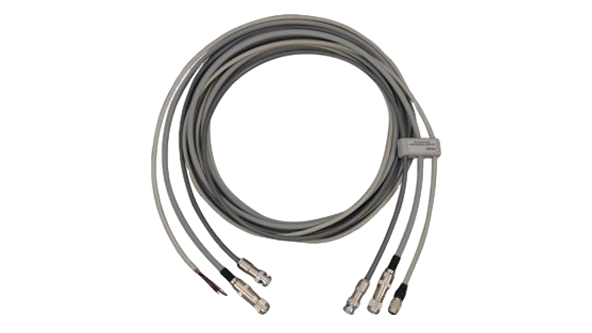
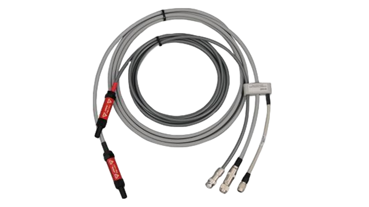
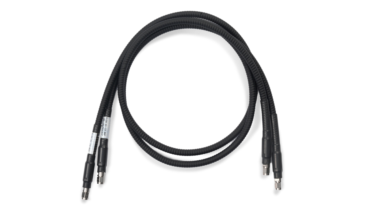
N2823A 电缆组件 详细指标
The N2823A is a low-loss, phase-matched, flexible coax cable assemblies with 1 m cable length…
一、InfiniiMax Ultra Probe Amplifier Specifications
条件:These are characteristics that are mainly determined by the probe amplifier.
With 25 kΩ probe heads With MX0105A SMA probe head
DC input resistance Rse = 25 kΩ
± 2% each input to
ground, Rdiff = 50 kΩ ± 2%
50 Ω (to Vterm)
Maximum input power N/A
100 mW or 2.28 Vrms (Vin-Vcm_term)
Input voltage range (differential or single- ended) 0.6 Vpp, ± 0.3 V @ 1:1 0.38 Vpp, ± 0.19 V @
1:1.56
2.5 Vpp, ± 1.25 V @ 4:1 1.54 Vpp, ± 0.77 V @
2.57:1
5.0 Vpp, ± 2.5 V @ 7.6:1 3.2 Vpp, ± 1.6 V @
4.87:1
Input common mode range ± 8 V (DC to 100 Hz) ± (4.3 V – Vcm_term x 0.29) (DC to 100 Hz) ± 0.5 V @ 1:1, ± 4 V @
4:1
± 0.19 V @ 1:1.57
± 0.77 V @
Maximum signal slew rate 25 V/ns when probing a SE signal 16 V/ns when probing a SE signal
40 V/ns when probing a differential signal
26 V/ns when probing a differential
DC attenuation ratio 1:1
4:1, or 7.6:1 automatically selected based on volts/division setting
automatically selected based on volts/division setting
Offset range (for probing a single-ended signal)
± 16 V
Zero offset error referred to input < 2 mV x DC attenuation <
2 mV
Input referred noise, in spectral density 25.0 nV/√(Hz) @ 1:1 16.0 nV/√(Hz) @ 1:1.56 39.7 nV/√(Hz) @ 4:1 25.5 nV/√(Hz) @
2.57:1
45.0 nV/√(Hz) @ 7.6:1 29.0 nV/√(Hz) @
4.87:1
Input referred noise, in mVrms 3.95 mVrms @ 1:1 and 25 GHz 2.26 mVrms @1:1.56 and 20 GHz 6.28 mVrms @ 4:1 and 25 GHz 3.61 mVrms @
2.57:1 and 20 GHz
7.10 mVrms @ 7.6 and 25 GHz 4.55 mVrms @
4.87:1 and 20 GHz
Propagation delay ~6.1 nsec
~6.1 nsec
Maximum non- destructive input voltage
30 V peak (mains isolated)
AutoProbe II interface – direct connection to Infiniium
90000X, V, Z, Q
UXR (3.5 mm models), requires N2852A adapter with UXR (1 and
1.85 mm models)
Oscilloscope compatibility
Infiniium UXR
90000X, V, Z, Q series with software
• Ver 6.70 or later (for
90000X, V, Z, Q models)
• Ver
11.20 or later (for UXR models)
For more information on the InfiniiMax Ultra Series, please see the
• 25 GHz bandwidth with an RC input impedance topology for low mid-band probe loading
• Enabling today’s emerging signaling standards including: LPDDR/DDR5, MIPI bus signaling and
other 高-速度信号 debug 和 validation 测试 needs
• Probe amp specific S parameter correction filter enabling high accuracy measurements
• Auto-switchable 1:1 and 4:1 attenuation ratio at full
25 GHz bandwidth
• Support for Keysight’s broad variety of probe heads and InfiniiMax I/II accessories
• AutoProbe II interface for easy direct connection to Keysight’s Infiniium Series Oscilloscopes
Keysight’s new MX0023A InfiniiMax RC probe provides high bandwidth and low loading, offering up to
25 GHz bandwidth and an RC input impedance profile for extremely low mid-band loading, which is
necessary to address modern high-speed probing requirements. It also provides a wide variety of
flexible connectivity solution, covering today’s emerging signaling standards such as DDR5/LPDDR5
和 other 高-速度信号 debug 和 validation 测试 needs
Characteristics performance plots: MX0023A
25 GHz probe amp with MX0100A micro probe
Frequency response of an ideal
25 GHz brickwall filter (red) and the typical DSP corrected probe
Time domain step responses for the two responses
CMRR for the
1:1 (red) and 4:1 (blue) mode.
InfiniiMax RC probing system family diagram
Characteristics (of MX0023A with each probe head)
主要指标 Probe amp 带宽 DC 输入电阻
MX0100A Micro probe head
(with 60 mil leads) MX0023A 25 GHz Rdiff = 50 kΩ
± 2%
二、InfiniiMax RC probe head Specifications
条件:• These are characteristics that are mainly determined by the probe head.
• Bandwidth and rise time numbers listed are
-3 dB bandwidth/10-90% transition time/20-80% transition
• Performance listed below is with the MX0023A probe amp.
• Refer to the MX0023A user’s guide for more details.
Characteristics (of MX0023A with each probe head)
Bandwidth and rise time (AmpBW/(.435/AmpBW)/ (.308/AmpBW))
MX0100A micro probe head
Cdiff=170 fF; Cse=260 fF
25 GHz/17.4 pS/12.3 pS Rdiff=50 kΩ; Rse=25 kΩ
MX0100A micro probe head
Cdiff= 170 fF, Cse=260 fF
12 GHz/36.3 pS/25.7 pS Rdiff=50 kΩ, Rse=25 kΩ
MX0106A solder-in probe head Cdiff=170 fF; Cse=290 fF
23 GHz/18.9 pS/13.4 pS Rdiff=50 kΩ; Rse=25 kΩ
N2839A browser Cdiff=205 fF; Cse=340 fF
21 GHz/20.7 pS/14.7 pS Rdiff=50 kΩ; Rse=25 kΩ
MX0105A SMA probe head N/A 21 GHz/21.8 pS/15.4 pS
50 Ω to Vterm
N5425B ZIF head with N5426A
Cdiff=330 fF; Cse=530 fF
18 GHz/24.1 pS/17.1 pS Rdiff=50 kΩ; Rse=25 kΩ
N5380B SMA head
N/A 12 GHz/36.3 pS/25.7 pS
50 Ω to Vterm
N5381B solder-in head Cdiff=210 fF; Cse=350 fF
12 GHz/36.3 pS/25.7 pS Rdiff=50 kΩ; Rse=25 kΩ
三、InfiniiMax RC probe amp Specifications
These are characteristics that are mainly determined by the probe amp.
With 25 kΩ probe heads With MX0105A SMA probe head
DC input resistance Rse = 25 kΩ
± 2% each input to
ground, Rdiff = 50 kΩ ± 2%
50 Ω (to Vterm)
Maximum input power N/A
100 mW or 2.28 Vrms (Vin-
Input voltage range (differential or single-ended) 0.6 Vpp, ± 0.3 V (at 1:1) 0.38 Vpp, ± 0.19 V (at 1:1.56) 2.5 Vpp, ± 1.25 V (at 4:1) 1.54 Vpp, ± 0.77 V (at
2.57:1)
Input common mode range ± 8 V (DC to 100 Hz) ± (4.3 V – Vcm_term x 0.29) (DC to 100 Hz) ± 0.5 V at 1:1
± 4 V at 4:1
± 0.19 V at 1:1.57
± 0.77 V at
Maximum signal slew rate 25 V/ns when probing a SE signal 16 V/ns when probing a SE signal
40 V/ns when probing a differential signal
26 V/ns when probing a differential
DC attenuation ratio
1:1 or 4:1, automatically selected
based on volts/division setting
1:1.56 or 2.57:1 automatically selected based on volts/division setting
Offset range (for probing a single-ended signal)
± 16 V
Zero offset error referred to input < 2 mV x DC attenuation <
2 mV
Input referred noise, in spectral density 25.0 nV/√(Hz) at 1:1 16 nV/√(Hz) at 1:1.56 39.7 nV/√(Hz) at 4:1
25.5 nV/√(Hz) at 2.57:1
Input referred noise, in mVrms 3.95 mVrms at 1:1 and 25 GHz 2.26 mVrms at 1:1.56 and 20 GHz 6.28 mVrms at 4:1 and 25 GHz
3.61 mVrms at 2.57:1 and 20 GHz
Propagation delay ~6.1 nsec
~6.1 nsec
Maximum non-destructive input voltage
30 V peak (mains isolated)
Probe interface AutoProbe II interface – direct connection to Infiniium
90000X, V, Z, Q
UXR ≤ 33 GHz models, requires N2852A with UXR ≥
40 GHz models
Oscilloscope compatibility
Infiniium UXR
90000X, V, Z, Q series with software
• Ver 6.55 or later (for
90000X, V, Z, Q models)
• Ver
10.25 or later (for UXR models)
• Full
30 GHz bandwidth to the probe tip
• InfiniiMode probing for making differential, single-ended and common
mode measurements with a single probe (InfiniiMax III+)
• Industry’s highest fidelity and accuracy due to bandwidth and extremely
• Probe amplifiers loaded with measured S-parameters for more accurate
• Bandwidth upgradeable (InfiniiMax III only)
• Variety of probe heads for different use models with maximum usability
条件:low loading to allow for a completely new level of signal fidelity and accuracy.
The InfiniiMax III/III+ probing system provides the highest performance and
Eleven different InfiniiMax III/III+ probe amplifiers ranging from 4 to 30 GHz
are available for matching your probing solution to your performance and
budget requirements. The InfiniiMax III+ probing system is the next
generation of InfiniiMax probing. It greatly expands the measurement
capability and usability of probes capable of measuring all components of a
differential signal with the built-in InfiniiMode technology.
InfiniiMax III amp with ZIF head/tips
N2830A InfiniiMax III+ amp with
Characteristics performance plots: N2803A 30-GHz probe amp with N5445A
30-GHz browser
Frequency response plot with 1 mm span
Time domain response plot with 1 mm span
InfiniiMax III/III+ probe heads
InfiniiMax III/III+ probe heads are recommended for InfiniiMax III N2801A/02A/03A, and InfiniiMax III+
N2830A/31A/32A and N7000A/01A/02A/03A probe amplifiers. Any probe heads for InfiniiMax I or II are
not compatible with InfiniiMax III or III+ amplifier and vice versa.
30 GHz, Cdiff =
35 fF, Cse =
50 fF, Rdiff =
100 kΩ, Rse =
50 kΩ
Z axis compliance and variable spacing from 20 mil to 125 mils, integrated LED lighting
ceramic tip 28 GHz, Cdiff = 95 fF, Cse = 130 fF, with N2838A: Cdiff = 32 fF, Cse =
44 fF, with
Extremely low loading, Variable spacing from 5 mil to 80 mil. User replaceable damping resistor tips (N2838A only)
2.92 mm/3.5 mm/
N5444A 30 GHz, N/A
55 Ω to Vterm
Provides termination voltage of
± 4 V controlled by scope or externally. Supports InfiniiMode with
26 GHz, Cdiff =
108 fF, Cse
For solder-in connection, variable span of leads ranges from 5 to 250 mil, user replaceable damping resistor tips. Supports extreme
operating temperature of –55 to
+150 °C per JEDEC JESD22-A104
revision E. Form, fit, function compatible with N2836A. Supports
条件:Economical and semi-permanent connection, variable span of leads ranges from 5 to 80 mil, user replaceable damping resistor tips.
26 GHz, Cdiff =
108 fF, Cse
N2836A supports InfiniiMode with
InfiniiMax III+ amp. N2836A
replaced the N5441A. N2836A has
–40 to +85 °C of operating
QuickTip tips
16 GHz (with InfiniiMax III/
III+)
13 GHz (with InfiniiMax
II), Cdiff = 340 fF, Cse =
200 fF
Magnetically-engaged probe head and tip for quick and secure connection, compatible with
I/II/III/III+ amp. Supports InfiniiMode with InfiniiMax III+ amp. For using
QuickTip with InfiniiMax I/II amp, choose the N2851A QuickTip head for InfiniiMax I/II and N2849A
Probe head Probe amp Bandwidth DC input
N5440A_N5439A ceramic
450 Ω
ZIF tip and ZIF probe head
amp 26 GHz Rdiff = 100 kΩ
± 2%
N5445A 450 Ω browser N2803A
30 GHz probe
amp 28 GHz Rdiff =1 00 kΩ
± 2%
MX0109A/N2836A
450 Ω solder-
in probe head vertical orientation with no ground wires
Differential mode N7003A
in probe head vertical orientation with no ground wires · InfiniiMax III/III+ probe head characteristics
条件:(0.434/AmpBW), (0.308/AmpBW), or bandwidth measured with the highest bandwidth amp in the family.
These characteristics are mainly determined by the probe head. Performance numbers listed are
–3 dB
bandwidth/10 to 90% transition time/20 to 80% transition time. Performance listed is with the highest bandwidth
probe amp models in each family. Performance with lower bandwidth amps is the lower of the: AmpBW,
InfiniiMax III+ N7003A
20-GHz
N5440A_N5439A
11.0 pS
15.4 pS N/A
N5447A_N5439A
11.0 pS N/A
N5445A 450 Ω browser Cdiff =
35 fF
10.3 pS
15.4 pS N/A
N2838A_N5439A PC
12.3 pS
20 GHz,
450 Ω solder-in probe
head vertical orientation with no ground wires
11.4 pS
15.4 pS N/A
450 Ω solder-in probe
head flat orientation with minimum length ground wires
11.4 pS
N2849A_N2848A
450 Ω QuickTip and
QuickTip probe head with ground wires connected
19.3 pS
11.0 pS
head · InfiniiMax III/III+ probe amp characteristics
These characteristics are mainly determined by the probe amp.
N280XA InfiniiMax III probe amp N700xA InfiniiMax III+ probe amp
2.92 mm, SMA,
3.5 mm probe
2.92 mm, SMA,
3.5 mm probe
± 2% each input
± 2% each input
and Rcm = 25 kΩ ± 2%
55 Ω to Vterm
± 2% each input
and Rcm = 25 kΩ ± 2%
55 Ω to Vterm
> 10 kHz
each input to ground, Rdiff =
1 kΩ and Rcm
= 250 Ω
each input to ground, Rdiff =
1 kΩ and Rcm
= 250 Ω
50 Ω to
0.901*Vterm
each input to ground, Rdiff =
1 kΩ and Rcm
= 250 Ω
50 Ω to
0.901*Vterm
or single- ended) 1.6 Vpp, ± 0.8 V (HD2&3 <
–38
± 1.25 V
dbc) 0.8 Vpp, ± 0.4 V (HD2&3 < –38 dbc)
1.6 Vpp
± 0.8 V (HD2&3
< –34 dbc)
± 1.25 V
dbc) 2.5 Vpp or
± 1.25 V at 5:1 attenuation
5.0 Vpp or
± 2.50 V at 10:1
attenuation 2.5 Vpp or
± 1.25 V at 5:1 attenuation
5.0 Vpp or
± 2.50 V at 10:1
Max input power N/A N/A
125 mW calculated by
{[rms(vin- vterm)]^2/55]} for each input
{[rms(vin- vterm)]^2/55]} for each input
± 12 VDC to
250 Hz,
± 1.25 V >
250 Hz
± 6 VDC to 250
> 250 Hz
± 6 VDC to
250 Hz,
± 1.25 V
> 250 Hz
without violating max input power
± 7 VDC to
100 Hz,
Hz at 5:1
attenuation, ± 2.5 V >
100
Hz at 10:1
attenuation ± 6 VDC to 100 Hz
± 1.25 V >
100 Hz at 5:1
attenuation, ± 2.5 V >
100 Hz at 10:1
DC attenuation ratio 6:1 3:1
6:1
5:1 or 10:1
Automatically selected based on volts/division (all modes)
5:1 or 10:1
ended signal) ± 16 V ± 8 V
± 6 V without
violating max input power ± 16 V
± 6 V without
Input referred noise spectral
density 23.9 nV/rt (Hz) 12.0 nV/rt (Hz)
23.9 nV/rt (Hz)
Diff 5:1 atten
33.5 nV/rt(Hz), Diff
10:1 atten
53.9 nV/rt(Hz), SE A or B
5:1 atten
27.8 nV/rt(Hz), SE A or B
10:1 atten
47.7 nV/rt(Hz), CM
5:1 atten
21.8 nV/rt(Hz), CM
10:1 atten
38.4 nV/rt(Hz)
Input referred noise example
4 mVrms with
28 GHz probe
head and 30
GHz probe amp
2 mVrms with 28 GHz probe head and 30
GHz probe amp 4 mVrms 4.5 mVrms in diff mode
5:1
probe head and 13 GHz probe amp
4.5 mVrms in diff
with 30 GHz
head and 13 GHz probe amp
Maximum input voltage
18 Vpeak mains
isolated 18 Vpeak mains isolated
8 Vpeak without
violating max input power
18 Vpeak mains isolated
8 Vpeak without
Model number Description Recommended oscilloscope
N2803A
30 GHz InfiniiMax III probe amplifier
Infiniium UXR (3.5 mm models), V, Z, Q, and
90000X Series, UXR (1 mm and 1.85 mm
models) with N2852A adapter, N1000A and
86100D DCA-X with N5477A adapter (only for
N2801A/02A/03A)
N2802A
25 GHz InfiniiMax III probe amplifier
N2801A
20 GHz InfiniiMax III probe amplifier
N7003A
20 GHz InfiniiMax III+ probe amplifier
N7002A
16 GHz InfiniiMax III+ probe amplifier
N7001A
13 GHz InfiniiMax III+ probe amplifier
N7000A
8 GHz InfiniiMax III+ probe amplifier
N2832A 13 GHz InfiniiMax III+ probe amplifier Infiniium MXR, EXR, S-Series
9000, and
90000A Series, UXR (3.5 mm models), V, Z,
Q, and 90000X Series with N5442A adapter,
UXR (1 and 1.85 mm models) with both
适用型号 N5442A 和 N2852A adapters
条件:Note: InfiniiMax III and III+ probe amps are not compatible with existing InfiniiMax I or II probe heads.
N2831A
8 GHz InfiniiMax III+ probe amplifier
N2830A
4 GHz InfiniiMax III+ probe amplifier
N2848A InfiniiMax III QuickTip
Supports InfiniiMode with InfiniiMax III+ amp
Order N2849A QuickTip tips (set of 4)
N5445A InfiniiMax III browser head Order N5476A for replacement probe tips (set of 4)
N5439A InfiniiMax III ZIF probe
Order N2838A PC board ZIF (450 Ω), N5440A ceramic ZIF
(450 Ω) or N5447A Ceramic ZIF (200 Ω) for a set of 5 ZIF
tips with plastic sporks. Order N2838-68701 (10x
130 ohm
resistors) for N2838A tip resistor replacement.
N5444A InfiniiMax III
2.92 mm/
3.5 mm/SMA probe head
Order N5448B (25 cm) or N2823A (1 m)
2.92 mm head flex
extreme temperature solder-in probe head
Supports
–55 to +150 °C of operating temperature range
and InfiniiMode with InfiniiMax III+ amp. Order N2838-
68701 (10x
130 ohm resistors) for tip resistor replacement.
N2835A InfiniiMax III/III+ differential
条件:Note: N54xxA InfiniiMax III/III+ probe heads are not compatible with InfiniiMax I or II probe amps.
Containing N5445A InfiniiMax III browser head (qty
1)
N2836A InfiniiMax III 26 GHz solder-in head (qty
2)
N5439A InfiniiMax III ZIF head (qty
2)
N2838A InfiniiMax III ZIF tip kit (qty
2)
N2848A InfiniiMax III QuickTip head (qty
2)
N2849A QuickTip tips (qty
2)
N5442A Precision BNC adapter (50 Ω)
For use with InfiniiMax I/II/III+
1130B/31B/32B/34B/68B/69B and
适用型号 N2830A/31A/32A probes, N2750A-52A
N2795A/96A/97A
1156A-58A etc.
N5449A High impedance probe adapter Includes one N2873A 500MHz
10:1 passive
N5477A Sampling scope adapter For InfiniiMax III amp to use with Keysight
86100C DCA-J sampling scope
N1022B Probe adapter For InfiniiMax III+ amp to use with 86100C
N5443A Performance verification and deskew
fixture For InfiniiMax III and InfiniiMax III+ >
13 GHz
E2655C Performance verification and deskew
fixture For InfiniiMax III+ <=13 GHz and InfiniiMax I/II
条件:Note: To upgrade the probe bandwidth, you simply need to send the probe to the Keysight service center.
N5446A-001
16 to 20 GHz bandwidth upgrade
N5446A-002
20 to 25 GHz bandwidth upgrade
N5446A-003
25 to 30 GHz bandwidth upgrade
N5446A-004
16 to 25 GHz bandwidth upgrade
N5446A-005
16 to 30 GHz bandwidth upgrade
N5446A-006
20 to 30 GHz bandwidth upgrade
Other recommended accessories for InfiniiMax III/III+ probing system
N2787A
3D probe positioner For hands-free probing
N5450B Extreme temperature extension
N2812A High performance input cable,
2.92 mm connectors
1 m length
For use with Infiniium V
90000-X/Q Series
N2823A Cable assembly, coax phase
matched pair, 1 m
2.92 mm (m) to 2.92 mm (m)
N5448B Cable assembly, coax phase
matched pair, 25 cm
2.92 mm (m) to 2.92 mm (m)
• Up to 13 GHz bandwidth for differential, solder-in, browser, and SMA
The InfiniiMax II Series
1168B/69B probing system provides real-time
bandwidth to 12 GHz specified and has
13 GHz typical performance. The
innovative InfiniiMax probing system supports even the most demanding
mechanical access requirements without sacrificing performance.
Characterized performance plots
1169B with N5381B differential solder-in probe head
Graph of Vin and Vout of 1169B and N5381B solder -in head with a 25 Ω
58 psec step generator
Frequency response of 1169B and N5381B with a
25 Ω source
Common mode rejection ratio of 1169B
InfiniiMax II Series probe amplifiers
条件:InfiniiMax probe amplifier specifications: Dynamic range = 3.3 V, DC offset range = ± 16 V, maximum voltage = ± 30 V.
Model number Bandwidth Description 1169B 12 GHz (spec)
13 GHz (typical)
InfiniiMax II probe amplifier – order one or more probe heads 1168B
10 GHz InfiniiMax II probe amplifier – order one or more probe heads
InfiniiMax II Series probe heads
InfiniiMax II Series probe heads are recommended for 1168B/69B probe amplifiers. When used with a
compatible Infiniium oscilloscope with >12 GHz bandwidth, the MX0100A, N5380B, N5381B, and
N2839A will typically achieve
13 GHz bandwidth.
Probe head Model number Differential measurement (BW, input C, input R)
Single-ended 测量 (BW, 输入 C, 输入 R)
Hi-BW Micro probe head MX0100A 12 GHz, 0.17 pF, 50 kΩ 12 GHz, 0.26 pF
25 kΩ
Hi-BW differential SMA N5380B 12 GHz
12 GHz
Hi-BW differential solder-in N5381B 12 GHz, 0.21 pF, 50 kΩ 12 GHz, 0.35 pF
25 kΩ
with N5426A 12 GHz, 0.33 pF, 50 kΩ 12 GHz, 0.53 pF
25 kΩ
0 deg 9.9 GHz, — , 50 kΩ 9.9 GHz, 0.6 pF
25 kΩ
0 deg 5 GHz, — , 50 kΩ 5 GHz, 0.68 pF
25 kΩ
with N2884A 12 GHz, 350 fF, 50 kΩ 12 GHz, 320 fF
25k Ω
QuickTip N2851A head with
N2849A tips 12 GHz, 0.2 pF, 50 kΩ 12 GHz, 0.34 pF
25 kΩ
Hi-BW differential browser N2839A 12 GHz, 0.21 pF, 50 kΩ 12 GHz, 0.34 pF
25 kΩ
InfiniiMax II differential connectivity kit N2833A
Containing N2839A InfiniiMax II browser head
N5381B InfiniiMax II solder-in head (qty
2)
N5425B InfiniiMax II ZIF head (qty
2)
N5426A ZIF tip kit (qty
2)
N2851A InfiniiMax II QuickTip head (qty
2)
N2849A QuickTip tips (qty
2)
Bandwidth 1 1169B: 12 GHz (13 GHz typical) 1168B: >
10 GHz
条件:1. Denotes warranted specifications, all others are typical.
2. Measured using the probe amplifier and solder -in differential probe head with full bandwidth resistors.
• When phase compensated by 90000A Series oscilloscope 1169B
28 ps (20 to 80%)
40 ps (10 to 90%)
48 ps (10 to 90%)
1169B with 91204A:
• 25 ps (20 to 80%)
• 36 ps (10 to 90%)
(20 to 80%)
1169B with 91304A:
• 23 ps (20 to 80%)
• 33 ps (10 to 90%)
54 ps (10 to 90%)
System bandwidth (–3 dB) 1169B with 91304A: 13 GHz (typical) 1168B with 90804A
8 GHz
Cm =
0.09 pF Cm is between tips
Cg =
0.26 pF Cg is to ground for each tip
Cdiff =
0.21 pF Differential mode capacitance = Cm + Cg/2
Cse =
0.35 pF Single-ended mode capacitance = Cm + Cg
Input resistance 1 Differential mode resistance = 50 kΩ
± 2%
Single-ended mode resistance = 25 kΩ
± 2%
Input dynamic range 3.3 V peak to peak
± 1.65 V
Input common mode range ± 6.75 V DC to 100 Hz; ± 1.25 V >
± 100 Hz
Maximum signal slew rate
25 V/ns when probing a single-ended signal
40 V/ns when probing a differential signal
Zero offset error referred to input
± 1.5 mV
Offset range
± 16.0 V when probing single-ended
Offset gain accuracy <
± 1% of setting when probing single-ended
Noise referred to input
2.5 mV rms, probe only
Propagation delay
~6 ns (this delay can be deskewed relative to other signals)
Maximum input voltage
30 V peak, mains isolated
ESD tolerance > 8 kV from 100 pF
300 Ω HBM
Temperature Operating
5 to +40 °C
• Up to 7 GHz bandwidth for differential, solder-in, browser, and SMA connections
• Wide dynamic range (± 2.5 V) and offset range (
± 12 V)
For high-speed differential or single-ended probing in embedded designs, the InfiniiMax
1130B Series
differential probe amplifiers are perfect complements to the Infiniium
600 MH to 6 GHz oscilloscopes. Its
extremely low input capacitance, flat frequency response and the patented resistor probe tip technology
provide ultra low loading of the DUT and superior signal fidelity.
Characterized performance plots: with E2677B differential solder-in probe head
Vin and Vout of probe with a 25 -Ω
100 psec step
Swept frequency response with a
25 -Ω source
Probe input impedance versus frequency Common mode rejection versus frequency
条件:1. Denotes warranted specifications, all others are typical.
2. Measured using the probe amplifier and solder -in differential probe head with full bandwidth resistors.
1130B/31B/32B/34B
Rise and fall time (10 to 90%)
System bandwidth (–3 dB)
1134B with DSO/DSA90604A
6 GHz
1132B with DSO/DSA90404A, DSO/MSO9404A
4 GHz
1131B with DSO/DSA90254A, DSO/MSO9254A
2.5 GHz
1130B with DSO/MSO9104A
1 GHz
1130B with DSO/MSO9064A
600 MHz
Cm =
0.1 pF Cm is between tips.
Cg =
0.34 pF Cg is to ground for each tip.
Cdiff =
0.27 pF Differential mode capacitance = Cm + Cg/2
Cse =
0.44 pF Singe-ended mode capacitance = Cm + Cg
Input resistance Differential mode resistance = 50 kΩ
± 2%
Single-ended mode resistance = 25 kΩ
± 2%
Input dynamic range
± 2.5 V
Input common mode range ± 6.75 V DC to 100 Hz; ± 1.25 V >
100 Hz
Maximum signal slew rate
18 V/ns when probing a single-ended signal
30 V/ns when probing a differential signal
DC attenuation 10:1
± 3% before calibration on oscilloscope
10:1
± 1% after calibration on oscilloscope
Zero offset error referred to input <
30 mV before calibration on oscilloscope
< 5 mV after calibration on oscilloscope
Offset range
± 12.0 V when probing single-ended
Offset accuracy <
3 % setting before calibration on oscilloscope
< 1 % setting after calibration on oscilloscope
Noise referred to input
3.0 mVrms
Propagation delay ~6 nsec (This delay can be deskewed relative to other signals.)
Maximum input voltage
30 Vpeak, mains isolated
ESD tolerance > 8 kV from 100 pF
300 Ω HBM
InfiniiMax I probe amplifier models
Model number Description Quantity 1134B 7 GHz InfiniiMax probe amplifier (order one or more probe heads or connectivity kits per amplifier) 1 1132B
5 GHz InfiniiMax probe amplifier (order one or more probe heads or
connectivity kits per amplifier)
1
1131B
3.5 GHz InfiniiMax probe amplifier (order one or more probe heads or
connectivity kits per amplifier)
1
1130B
1.5 GHz InfiniiMax probe amplifier (order one or more probe heads or
connectivity kits per amplifier)
1
条件:InfiniiMax connectivity kit for differential/single-ended measurements.
Includes one differential browser, four solder-in differential probe heads and
two socketed differential probe heads. Includes all necessary accessories
InfiniiMax connectivity kit for single-ended measurements. Includes one
single-ended browser, one solder-in probe heads and one socketed probe
InfiniiMax differential browser probe head and accessories. Includes
20
replaceable tips and ergonomic handle. Order E2658A for replacement
InfiniiMax single-ended browser probe head and accessories. Includes
2
ground collar assemblies
10 replaceable tips, a ground lead socket, and
ergonomic handle. Order E2663A for replacement accessories
InfiniiMax differential solder-in probe head and accessories. Includes
20 full
bandwidth and 10 medium bandwidth damping resistors. Order E2670B for
条件:InfiniiMax single-ended/differential socketed probe head and accessories.
Includes 48 full bandwidth damping resistors, 6 damped wire accessories
4
square pin sockets, and socket heatshrink. Order E2671A for replacement
InfiniiMax single-ended solder-in probe head and accessories. Includes
16
full bandwidth
8 medium bandwidth damping resistors, and 24 zero ohm
ground resistors. Order E2672A for replacement accessories
N1022B Adapts InfiniiMax I/II active probes to 86100 Infiniium DCA
1
N2887A InfiniiMax Soft touch pro probe adapter (36 channel, up to 4 GHz)
1
N2888A InfiniiMax Soft touch half-channel probe adapter (18 channel, up to 4 GHz)
1
Optical-to-Electrical Converters — N7005A
60 GHz
• DC to 60 GHz typical (–3 dBe, electrical)
• 9/125 µm, 1250 nm - 1600 nm (covers main wavelengths
1310 nm, and 1550 nm)
• FlexDCA SW supports PAM4 measurement capabilities such as TDECQ
• Optical measurement features built into the Infiniium UXR baseline software version
• 10.25 patch or higher
• Compatible with Infiniium UXR oscilloscope with ≥
40 GHz bandwidth
The N7005A is a
60 GHz (-3 dB, Brickwall) O/E converter compatible with Keysight UXR oscilloscope
with 1.85 mm or 1 mm input. The frequency response of a DSP corrected N7005A is either flat to up to
60 GHz Brickwall response or it follows a 4th order Bessel Thomson response until it hits the Brickwall
at 70 GHz. The N7005A used in conjunction with 70 GHz Infiniium UXR oscilloscope supports
4th order
Bessel Thomson response to view optical streams at speeds up to 56 Gbaud PAM4, making this the
ideal solution for characterizing or troubleshooting high-speed optical signals in system level testing and
条件:deep analysis of PAM4 signaling measurement capabilities such as TDECQ.
Infiniium UXR baseline software v 10.25 patch or higher covers basic optical measurement features and
dark calibration. The FlexRT measurement software installed on Infiniium UXR oscilloscope supports
Optical-to-Electrical Converters — N7004A
33 GHz
• DC to 33 GHz typical (–3 dBe, electrical)
• Single-模式和 multimode 输入
• 50/125 μm
750 to 1650 nm (covers main
wavelengths: 850 nm
1310 nm, and 1550 nm)
• Designed for reference receiver testing of industry optical standards or characterizing raw response of an optical transmitter
• Optical measurement features built into the
Infiniium baseline software version
05.70 or
• Compatible with Infiniium UXR, V-Series
90000
X-Series, Z-Series and discontinued
90000 Q-
Series real-time oscilloscopes
The Keysight N7004A optical-to-electrical converter is a high-sensitivity photodetector module designed
for direct optical-to-electrical conversion of optical telecom or data com signals into an Infiniium real-time
oscilloscope with AutoProbe II interface
条件:directly into the AutoProbe II probe interface of the Infiniium oscilloscope.
users who want to see the unfiltered response of optical transmissions as well.
data is used to flatten the frequency response for more accurate measurement.
The N7004A is the first fully-integrated optical-to-electrical converter solution for Infiniium real- time
oscilloscopes. A full suite of optical measurement software is built into the Infiniium baseline software v
05.70 and is offered at no additional cost. The N7004A comes in a compact form factor that is plugged
The adapter provides from DC to 33 GHz of electrical bandwidth. When used with an Infiniium V-Series
or Z-Series
33 GHz oscilloscope, the N7004A allows users to view optical streams at speeds up to 28
Gbps, making this the ideal solution for characterizing or troubleshooting high-speed optical signals in
the system level testing. The N7004A with an Infiniium real-time oscilloscope is the ideal solution for
Each N7004A adapter contains its unique S-parameter correction filter, and this frequency response
The input is a
50 μm/125 μm fiber that can be used with 9 μm single-mode fiber or 50 μm multimode
fiber at wavelengths from 750 to 1650 nm and has a FC/PC adaptor. The reference receiver
measurement is made with a built-in 4th order Bessel Thomson software filter that allows the waveform
to be viewed similarly to what an optical receiver in an actual communication system would display. The
4th order Bessel Thomson filter bandwidth is limited to 2/3 of the Brickwall bandwidth of the
oscilloscope. For a 33 GHz oscilloscope with the Bessel Thomson filter on, this yields a
22 GHz Bessel
Thomson filter, which covers 28 Gbps x 0.75 =
21 GHz.
–3 dBe)
33 GHz (with Brickwall filter)
60 GHz (with Brickwall filter)
22 GHz (with
4th order Bessel
Thomson filter) 46.6 GHz (with
4th order Bessel
Bandwidth, warranted (electrical, –3 dBe) 32 GHz (with Brickwall filter) 21.3 GHz (with
4th order Bessel
Rise time (10 to 90%), typical
13.3 psec (with Brickwall filter)
7.3 psec (with Brickwall filter)
17.7 psec (with
4th order Bessel
Thomson filter) 8.4 psec (with
4th order Bessel
Rise time (20 to 80%), typical
9.4 psec (with Brickwall filter)
5.2 psec (with Brickwall filter)
12.3 psec (with
4th order Bessel
Thomson filter) 5.8 psec (with
4th order Bessel
Wavelength range 750 to 1650 nm
1250 to 1600 nm
RMS noise (μW) See the noise characteristics table on the N7005A user’s guide
Conversion gain (V/W) 850 nm MM: 68 (min), 75 (typical) 1310 nm MM/SM: 105 (min)
110 (typical)
(typical) 1550 nm SM: 105 (min), 110 (typical) 1550 nm SM: 72 (min)
85
Maximum linear input power
4 mW
8 mW
Input return loss (dB) 850 nm MM: –17 (typical), –15 (max) (fully filled fiber) 1310 nm SM: –18.5 (typical)
–16
(max) 1310 nm SM
–25 (max)
1550 nm SM: –14 (typical) 1550 nm SM
–25 (max)
FC/PC to 50/125 um fiber,
compatible with single-mode or multimode fiber
FC/PC to 9/125 um fiber,
Optical measurements in watts, extinction ratio with dark calibration,
eye mask testing (including ability to load DCA masks with margin and
user defined mask support), power of 1 and 0, optical modulation
amplitude, average power, remote command support for all new features.
Oscilloscope compatibility
Infiniium UXR, V
90000X, Z
series and discontinued
90000 Q
Infiniium UXR with 40 GHz or
Oscilloscope software compatibility
Infiniium software version
05.70
or higher for Infiniium non-UXR Infiniium software version
10.25
for UXR models Infiniium software version
10.25
条件:Figure 1. A full suite of optical measurement software is built into the Infiniium baseline software.
Active Termination Adapter — N7010A
• 30-GHz single-ended active termination adapter supporting
2.92 mm/3.5 mm/SMA cable input
• Low attenuation setting (1.16:1) for high SNR, low noise
条件:definition. However, a particular communication system often requires
• Ability to terminate signal to a
50 Ω non-ground voltage (VTERM)
• Compatible with Infiniium UXR
90000Q, Z-Series, or V-Series
installed with software version 5.30 or higher, and Infiniium
90000X
with 5.50.0030 or higher
To date, most oscilloscopes with 50 Ω inputs terminate to ground by
the
50 Ω termination to a voltage rather than to ground. The Keysight
N7010A active termination adapter is a
30-GHz single-ended adapter
featuring a user-adjustable common termination voltage (VTERM) and
extremely low noise performance. The termination voltage between –
4.0 to +4.0 V can be controlled internally by the oscilloscope. The
N7010A is a single-ended adapter. Two scope channels and two
adapters are needed for making differential measurement, which allow
the A-to-GND, B-to-GND and differential (A-B) signals to be viewed in
Utilizing low attenuation ratio setting (1.16:1), the adapter enables an extremely lower noise floor,
especially at high-sensitivity vertical scales (<
400 mV) when compared to the Keysight InfiniiMax III
probe with the N5444A SMA/2.92 mm head.
Key characteristics and specifications N7010A
Bandwidth 1 30 GHz (warranted)
32 GHz (typical)
Rise time (10 to 90%)
14.5 ps
Noise with oscilloscope See chart
条件:1. Warranted specifications.
Vin max active signal
1.2 Vpp (not including DC component)
Input signal range (|Vin - Vterm| difference) —0.6 V ≤ (Vin — Vterm ) ≤
+0.6 V
Input resistance at DC 1 50 Ω
± 3 %
Max non-destructive input voltage
± 8 V
Figure 2. Direct signal connect to Infiniium scope Figure
3. Signal through N7010A active termination
adapter; N7010A not inherently contribute noise
Eye diagram comparison with MIPI ® M- PHY® Gear 3 data rate at 5.8304 Gb/s, amplitude swing: =
140 mVpp
Noise of N71010A with Infiniium V-Series oscilloscopes
InfiniiMode Active Probes — N2750A/51A/52A
InfiniiMode active probes N2750A/51A/52A InfiniiMode probes
• 1.5
3.5, and 6 GHz probe bandwidth models
• Dual attenuation ratio (2:1/10:1)
• High input resistance (200 kΩ differential
100 kΩ single-ended)
• Wide input dynamic range (10 Vpp) and offset range (
± 15 V)
• High CMRR (>
60 dB at 1 MHz)
• InfiniiMode probing for making differential, single-ended, and
• Built-in quick action scope control for quick access to a variety of
• Includes solder-in, browser, and socketed tips standard
• AutoProbe interface for auto configuration and probe power for
The N2750A Series differential probes offer
2:1 and 10:1 dual attenuation settings, allowing them to be
used for a broad range of applications. Dual attenuation range is automatically configured depending on
The new differential probes have an input resistance of 200 kΩ (differential) or 100 kΩ (each input to
ground) and an extremely low input capacitance of 700 fF to minimize circuit loading. This,
accompanied with superior signal fidelity, makes these probes useful for most digital design and debug
applications. And with their wide dynamic range (10 Vpp) and offset range (
± 15 V), these probes can
be used in a wide variety of analog signal measurements as well.
The N2750A Series probes come with new InfiniiMode operation modes. The InfiniiMode allows
convenient measurements of differential, single- ended, and common mode signals with a single probe
tip without reconnecting the probe to change the connection. The N2750A probe’s InfiniiMode provides
• B – ground (single-ended B)
• (A+B)/2 – ground (common mode)
The N2750A Series InfiniiMode differential
probes are a new generation of low-cost, 1.5
3.5, and 6 GHz differential active probes compatible with Infiniium oscilloscope’s AutoProbe interface
Quick action scope control
The N2750A Series differential probes provide convenient and quick access to various functions on the
scope. You often have a need to control the scope while you hold a probe in your hand. With the quick
action scope control feature built into the probe, you can turn the built-in headlight of the probe on and
off or control some frequently used scope functions, such as RUN/STOP, auto scale, quick print, and
quick save with only the push of a button on the probe. Get control of your most needed function with a
push of the quick action control button on the probe
Flexibility in probe use models is also a vital necessity. The probes come standard with three different
types of exchangeable probe tips that allow for easy connections to the circuit under test. These probe
tips enable you to access multiple signals on anything from header connectors to hard-to- reach, high-
density circuitry. The probes are equipped with a white LED headlight to illuminate the circuit under test
which will help you see where you are probing
The probes are powered directly by the Infiniium AutoProbe interface, eliminating the need for an
The InfiniiMode probe allows convenient measurements of differential, single- ended (A and B) and
适用型号型号编号 N2750A N2751A N2752A
(–3 dB) 1.5 GHz 3.5 GHz
6 GHz (warranted)
7 GHz (typical)
Rise time, probe only (10 to 90%) 233 psec 100 ps
58.3 ps
Keysight oscilloscope)
1 GHz (with Keysight’s
Infiniium oscilloscope)
2.5 GHz (with
Keysight’s Infiniium oscilloscope)
4/6 GHz (with
Keysight’s Infiniium oscilloscope)
Input resistance (at DC)
1
(differential mode) 100 kΩ ± 2% (single- ended mode) 50 kΩ
± 2% (common
条件:Maximum non-destructive input voltage ± 30 V (DC + peak AC) mains isolated 1. Denotes warranted electrical specifications at 2:1 attenuation mode after 20 minute warm -up. All others are typical.
2. When calibrated on the oscilloscope, these characteristics are determined by the oscilloscope characteristics.
3. Assumes symmetric differential signals.
Input capacitance
700 fF (with browser)
Attenuation ratio (at DC)
2:1 / 10:1
Input dynamic range ± 1 V, 2 Vpp (at
2:1)/
Input common mode range ± 15 V (from DC to 100 Hz)
± 2.5 V (for
Vout /Vin frequency response of N2752A (at
2:1) with browser tip
Common mode rejection ratio (red= 2:1, blue=
10:1)
Vout /Vin frequency response of N2752A (at
2:1) with browser tip
N2750A
1.5 GHz InfiniiMode differential probe
N2751A
3.5 GHz InfiniiMode differential probe
N2752A
6 GHz InfiniiMode differential probe
N2776A Differential browser tips (qty
3)
N2777A InfiniiMode solder-in tips (qty
3)
N2778A InfiniiMode socketed tips (qty
3)
N4822A Socketed tip for USB/Ethernet application fixtures (qty
1)
The N2750A/51A/52A InfiniiMode probes include two browser tips, two socketed tips, and two solder-in
tips as standard. The N4822A is not included in the N2750A-52A probe.
N2787A
3D probe positioner
E2655C Performance verification and deskew fixture
N5442A Precision BNC adapter for V-Series
90000X/Q Series oscilloscopes
For more information about the N2750A Series InfiniiMode probes, refer to the data sheet with the
Keysight literature number
5991-0560EN.
socketed tip for application fixtures
Single-Ended Active Probes — N2795A/96A/97A
• High resistance (1 MΩ) and low capacitance (1 pF) input for low
• Wide input dynamic range (± 8 V) and offset range (
± 12 V for
N2796A/97A
± 8 V for N2795A)
• Direct connection to AutoProbe interface (no power supply required)
• N2797A for extreme temperature environmental chamber testing at
–40 to +85 °C
The N2795A/96A are a new generation of low-cost
1 to 2 GHz single-
ended active probes with the AutoProbe interface (compatible with
Keysight’s Infiniium family of oscilloscopes). These probes integrate
many of the characteristics needed for today’s general-purpose, high-
speed probing–especially in digital system design, component design/characterization, and educational research applications. Its 1 MΩ input resistance and extremely low input capacitance (1 pF) provide ultra low loading of the DUT. This, accompanied with superior signal fidelity
makes these probes useful for most of today’s digital logic voltages.
Testing devices over extreme temperature ranges is quite common these
days. The N2797A
1.5 GHz single-ended active probe is the industry’s
first low-cost high input impedance active probe with rugged probe tips
for environmental chamber testing of ICs and devices. The probe gives
the ability to probe signals at drastic temperature swings ranging from –
40 to +85 °C. The probe provides a
2-m long cable. Order N2798A for
The N2795A/96A/97A are equipped with a white LED headlight to
illuminate the circuit under test. The probes are powered directly by the
Infiniium AutoProbe interface, eliminating the need for an additional
power supply. The probes also come with a number of accessories that
allow for easy connections to the circuit under test
For more information about N2795A/96A/97A active probe, refer to the
Keysight N2795A/96A/97A active probe data sheet literature number
5990-6480EN.
Characteristics for N2795A, N2796A, and N2797A active probes
适用型号 N2795A N2796A N2797A
Probe bandwidth 1 (-3 dB) 1 GHz 2 GHz
1.5 GHz
Rise time 350 ps 175 ps
233 ps
System bandwidth 600 MHz (with Keysight’s
600 MHz Infiniium oscilloscope)
1 GHz (with Keysight’s
1 GHz Infiniium
条件:1. Denotes warranted electrical specifications after 20 minute warm -up. All others are typical.
Attenuation ratio (at DC) 10:1
± 0.5%
Input dynamic range
-8 to +8 V (DC or peak AC)
Non-destructive input voltage
-20 to +20 V mains isolated
DC offset error (output zero)
± 1 mV
Low frequency accuracy 0.5% at 70 Hz
1 Vpp
Time domain step response of N2796A
(with Keysight MSO9404A)
Frequency response of N2796A (Vout/Vin)
N2795A
1 GHz single-ended active probe
N2796A
2 GHz single-ended active probe
N2797A
1.5 GHz single-ended active probe
N4839A Dual-lead socketed adapter, 6 cm
2
N4840A Dual-lead solder-in adapter, 5 cm
2
N4841A Dual-lead socketed adapter, 9 cm
2
N4842A Dual-pin PCB header
2
N4844A Right angle ground lead, 5 cm
2
Voltage derating over frequency (N2796A)
Power Rail Probes — N7020A
2 GHz Power Rail Probe
• 2- GHz single-ended active probe for power rail noise measurement
• 1.1:1 attenuation ratio ensures low noise signal measurement
•
± 24 V of probe offset range enables effective elimination of DC
component of a power supply
The N7020A power rail probe is a low noise, large offset range
oscilloscope probe that enables users to measure small signals riding
on top of DC power supplies
• Low noise: The N7020A power rail probe is a
1:1 attenuation ratio
active probe. As a general rule, the higher a probes attenuation
ratio, the nosier the signal will be on the oscilloscope
• Large offset range: The N7020A power rail probe provides
± 24 V
of probe offset. This enables users to center the signal on screen
while placing the oscilloscope at its maximum vertical sensitivity
• Low DC loading: The N7020A power rail probe has
50 kΩ input
impedance at DC, minimizing the probe’s DC loading of the power
条件:measuring programmable supplies like those used in micro- controller power saving modes.
• Large input dynamic range: The N7020A power rail probes
± 850 mV input dynamic range means that users can measure up
to 850 mV deviations of their DC supplies. This is very useful for
• Supporting three connection options: pigtail solder head (2 GHz),
SMA (2 GHz), browser (350 MHz).
Probe bandwidth (–3 dB)
2 GHz
Input impedance at DC 50 kΩ
± 2%
Input dynamic range
± 850 mV about offset voltage, mains isolated
Probe noise
10% of oscilloscope noise
N7021A coaxial probe head (qty
3)
N7022A SMA main cable
N7023A browser kit
Compatible oscilloscopes Infiniium S-Series or 9000 Series with software rev.
5.20 or higher
N7023A (included in the N7020A
and orderable separately)
Power Rail Probes — N7024A
6 GHz Power Rail Probe
• 6 GHz single-ended active probe for power integrity measurements
in high speed systems where fast switching loads and transients
can lead to failure due to Power Supply Induced Jitter
• 1.3:1 attenuation ratio maximizes the signal-to-noise ratio of the
•
± 15 V probe offset range enables power integrity measurements of
the power rails encountered in high speed systems
The N7024A power rail probe is similar to the N7020A power rail
probe in that they both were designed to provide the user the
ability to zoom-in on their DC power supplies to accurately observe
and measure the ripple, noise and transients riding on these supply
outputs. The N7024A is for the engineer or technician who would
like to use one oscilloscope for both their SI and PI measurements
using Keysight’s Infiniium oscilloscopes. The N7024A includes
multiple connection options: SMA connection (6 GHz), N7021A
pigtail coax (~6 GHz), N7033A fine pitch SMT browser (5 GHz),
N7032A fine pitch SMT browser (4 GHz) and N7023A general
purpose browser (350 MHz).
以上指标摘自厂家官方数据手册,完整定义、测试条件与保证值口径以手册为准。完整指标、测试条件与定义口径请见产品页「软件和手册 | 白皮书」栏目中的官方数据手册。
是德科技 | KEYSIGHT · onetest 仪器资源库


 客服








 粤公网安备44030902003758