是德科技 | KEYSIGHT
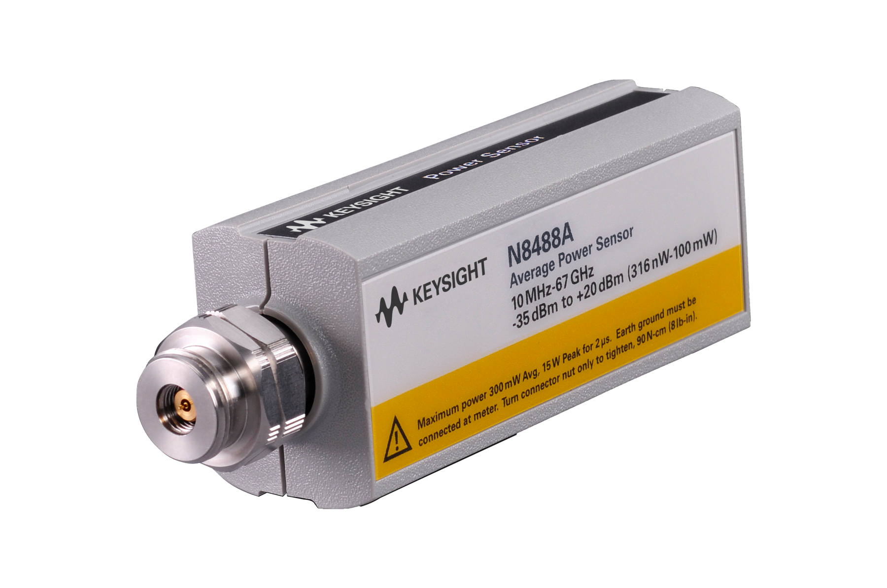
N8488A 10MHz至67GHz 功率传感器 20dBm(100mW) 详细指标
条件:characteristics are shown in italics or denoted as “typical,” “nominal” or “approximate.”
Characteristic specifications are not warranted. They describe product performance that is useful in the
application of the power sensors by giving typical, but non-warranted performance parameters. These
Characteristic information is representative of the product. In many cases, it may also be supplemental
Characteristic specifications are not verified on all power sensors. The types of characteristic
specifications can be placed in two groups
条件:a 50‑Ω input is nominal. These two terms are most widely used when describing a product’s
• The first group of characteristic types describes ‘attributes’ common to all products of a given
model or option. Examples of characteristics that describe attributes are product weight and
50‑Ω input Type‑N connector. In these examples, product weight is an approximate value and
• The second group of characteristic types describes ‘statistically’ the aggregate performance
of the population of products. These characteristics describe the expected behavior of the
population of products. They do not guarantee the performance of any individual product. No
measurement uncertainty value is accounted for in the specification. These specifications are
The power meter and power sensor meet their specifications when:
• Stored for a minimum of two hours at a stable temperature within the operating temperature range
and turned on for at least
30 minutes
• The power meter and power sensor are within their recommended calibration periods
• Used in accordance to the information provided in the power meter’s user’s guide
条件:Specifications stated hereon refer to all N8480 Series power sensors, unless otherwise stated. The term
“standard” refers to all N8480 Series sensors except Option CFT.
Sensor option Sensor model Frequency range Dynamic power range
–35 to +20 dBm
N8485A - Option 033
10 MHz to 33 GHz
67 GHz to 70 GHz
N8481B 10 MHz to 18 GH –5 to +44 dBm N8482B
100 kHz to 6 GHz
N8481H 10 MHz to 18 GHz –15 to +35 dBm N8482H
100 kHz to 6 GHz
–30 to +20 dBm
N8485A - Option 033
10 MHz to 33 GHz
N8481B 10 MHz to 18 GHz 0 to +44 dBm N8482B
100 kHz to 6 GHz
N8481H 10 MHz to 18 GHz –10 to +35 dBm N8482H
100 kHz to 6 GHz
Sensor model Damage level (average power) Damage level (peak power)
N8481B N8482B +49 dBm
500 W/1 μs N8481B N8482B
N8481H N8482H +40 dBm
100 W/1 μs N8481H N8482H
Sensor model Frequency band 25 ± 10 °C
0 to 55 °C
> 30 to 50 MHz 1.14
1.16
> 50 MHz to 2 GHz 1.08
1.11
> 2 to 12.4 GHz 1.16
1.16
> 12.4 to 18 GHz 1.23
1.25
> 300 kHz to 1 MHz 1.17
1.17
> 1 MHz to 2 GHz 1.06
1.06
条件:1. Only applicable for N8485A Option 033.
> 50 to 100 MHz 1.08
1.11
> 100 MHz to 2 GHz 1.05
1.07
> 2 to 12.4 GHz 1.14
1.14
> 12.4 to 18 GHz 1.19
1.20
> 18 to 26.5 GHz 1.26
1.28
> 26.5 to 33 GHz 1 1.32
1.36
> 100 MHz to 2 GHz 1.05
1.07
> 2 to 12.4 GHz 1.10
1.10
> 12.4 to 18 GHz 1.16
1.16
> 18 to 26.5 GHz 1.22
1.22
> 26.5 to 40 GHz 1.30
1.30
> 40 to 50 GHz 1.34
1.33
>100 MHz to 2.4 GHz 1.08
1.08
> 2.4 to 12.4 GHz 1.10
1.10
> 12.4 to 18 GHz 1.12
1.14
> 18 to 26.5 GHz 1.21
1.23
> 26.5 to 40 GHz 1.30
1.31
> 40 to 67 GHz 1.46
1.47
> 67 to 70 GHz 1.48
1.50
N8486AR 50 MHz 2 1.17
1.20
N8486AQ 50 MHz 2 1.17
1.20
> 2 to 12.4 GHz 1.14
1.18
> 12.4 to 18 GHz 1.23
1.28
N8482B 100 kHz to 2 GHz 1.08
1.10
条件:2. SWR for 50 MHz calibration port. Type -N (m) coaxial connector is used in the 50 MHz calibration.
> 8 to 12.4 GHz 1.22
1.22
> 12.4 to 18 GHz 1.32
1.41
N8482H 100 kHz to 6 GHz 1.13
1.14
Typical SWR, 10 MHz to 18 GHz (25
± 10 °C) for
Typical SWR, 100 kHz to 6 GHz (25
± 10 °C) for
Typical SWR, 10 MHz to 26.5 GHz (25
± 10 °C) for
Typical SWR, 50 MHz to 50 GHz (25
± 10 °C) for
N8487A power sensor
Typical SWR, 10 MHz to 70 GHz (25
± 10 °C) for
N8488A power sensor
Typical SWR, 33 to 50 GHz (25
± 10 °C) for
N8486AQ power sensor
Typical SWR, 26.5 to 40 GHz (25
± 10 °C) for
N8486AR power sensor
Typical SWR, 10 MHz to 18 GHz (25
± 10 °C) for
N8481B power sensor
Typical SWR, 100 kHz to 6 GHz (25
± 10 °C) for
N8482B power sensor
Typical SWR, 10 MHz to 18 GHz (25
± 10 °C) for
N8481H power sensor
Typical SWR, 100 kHz to 6 GHz (25
± 10 °C) for
N8482H power sensor
The N8480 Series power sensors’ linearity is negligible except for the power range specified in the table
Sensor model Power range Linearity (25
±10 °C) Linearity (0 to 55 °C)
条件:1. After zero and calibration at ambient environment conditions .
–1 to < +15 dBm ± 0.52%
± 0.80%
+15 to +20 dBm ± 0.80%
± 1.90%
N8481B, N8482B +29 to < +39 dBm ± 0.52%
± 0.80%
+39 to +44 dBm ± 1.66%
± 2.75%
N8481H, N8482H +17 to < +30 dBm ± 0.77%
± 1.05%
+30 to +35 dBm ± 2.84%
± 3.93%
条件:Typical N8481A/2A/5A/7A/8A and N8486AR/AQ power linearity at 25 °C, after zero and calibration with associated
条件:Typical N8481B/2B power linearity at 25 °C, after zero and calibration with associated measurement uncertainty
Power level Measurement uncertainty 29 to 40 dBm ± 0.35% 40 to 44 dBm
± 1.21%
Power level Measurement uncertainty 17 to 30 dBm ± 0.60% 30 to 35 dBm
± 2.39%
Standard Upper Up to 70% ± 63 nW < ± 7 nW <
114 nW
Lower Up to 70 % ± 25 nW < ± 3 nW <
80 nW
Option CFT N/A 5 Up to 70% ± 63 nW < ± 7 nW <
114 nW
N8488A Standard Upper Up to 70% ± 63 nW < ± 7 nW <
114 nW
Lower Up to 70 % ± 25 nW < ± 3 nW <
80 nW
Option CFT N/A 5 N/A 5 N/A 5 N/A 5 N/A
5
Standard Upper Up to 70% ± 63 μW < ± 7 μW <
114 μW
Lower Up to 70 % ± 25 μW < ± 3 μW <
80 μW
Option CFT N/A 5 Up to 70% ± 63 μW < ± 7 μW <
114 μW
条件:1. RH is the abbreviation for relative humidity.
2. Average hourly drift, at constant temperature. If there is an abrupt change of temperature, it is strongly recommended to perform
3. The number of averages at 16 for normal mode and 32 for x2 mode, at a constant temperature, measured over one- minute interval
Typical N8481H/2H power linearity at 25°C, after zero and calibration with associated measurement uncertainty
Standard Upper Up to 70% ± 6.3 μW < ± 0.7 μW <
11.4 μW
Lower Up to 70 % ± 2.5 μW < ± 0.3 μW <
8 μW
Option CFT N/A 5 Up to 70% ± 6.3 μW < ± 0.7 μW <
11.4 μW
zeroing or waiting for 30 minutes before taking the measurement.
and two standard deviations. 4. The zero set, zero drift, and measurement noise specifications are tested at 50 MHz .
5. N/A is the abbreviation for “not applicable.”
Averaging over 1 to 1024 readings is available for reducing noise. The table below provides the
measurement noise for a sensor with the number of averages set at 16 (for normal mode) and 32 (for x2
mode). Use the noise multiplier, for the appropriate mode (normal or x2) and number of averages, to
N8481A power sensor, normal mode, number of averages =
4
< 80 nW x 2.75 = <
220 nW
Number of averages 1 2 4 8 16 32 64 128 256 512
1024
Normal mode 5.5 3.89 2.75 1.94 1 0.85 0.61 0.49 0.34 0.24 0.17 x2 mode 6.5 4.6 3.25 2.3 1.63 1 0.72 0.57 0.41 0.29
0.2
The N8480 Series power sensors (excluding Option CFT) have two measurement ranges: a lower
power range and an upper power range. The power meter automatically selects the proper power level
range. To avoid unnecessary switching when the power level is near the switch point, switching point
hysteresis has been added
N8481A/82A/85A/87A/88A and N8486AQ/AR power sensors
This hysteresis causes the lower power range to remain selected until approximately
–0.5 dBm as the
power level is increased. Above this power, the upper power range is selected. Likewise, the upper
power range remains selected until approximately
–1.5 dBm as the signal level decreases. Below this
条件:power level is increased. Above this power, the upper power range is selected.
power level is increased. Above this power, the upper power range is selected.
N8481B/82B power sensors
This hysteresis causes the lower power range to remain selected until approximately
29.5 dBm as the
Likewise, the upper power range remains selected until approximately
28.5 dBm as the signal level
decreases. Below this power, the lower power range is selected.
N8481H/82H power sensors
This hysteresis causes the lower power range to remain selected until approximately
17.5 dBm as the
Likewise, the upper power range remains selected until approximately
16.5 dBm as the signal level
decreases. Below this power, the lower power range is selected.
AUTO (default) -35 to –1 dBm
-1 to +20 dBm
AUTO (default) -5 to +29 dBm
+29 to +44 dBm
条件:1. Recommended for pulse signals measurement with period of more than one second.
Manual filter, 10-dB decreasing power step for normal and x2 modes (not across switching point).
Normal mode 0.15 0.2 0.3 0.5 1.1 1.9 3.4 6.6 13 27 57 x2 mode 0.15 0.18 0.22 0.35 0.55 1.1 1.9 3.5 6.9 14.5 33 1. Settling time: 0 to 99% settled readings over the GPIB.
AUTO (default) -15 to +17 dBm
+17 to +35 dBm
Number of averages 1 2 4 8 16 32 64 128 256 512
1024
Auto filter, default resolution
10-dB decreasing power step for normal and x2 modes (not across
Calibration factor and reflection coefficient
条件:meters automatically read the CF data stored in the sensor’s EEPROM and use it to make the corrections.
The reflection coefficient (Rho or ρ) relates to the SWR according to the following formula:
Maximum relative measurement uncertainties of the calibration factor (CF) are listed in the following table.
1. The characterized calibration factor should not deviate between periodic calibrations by more than the specified maximum relative
maximum uncertainty. √2 ∗UUUUUUUU with a reference calibration factor of 100%.
Calibration factor (CF) and reflection coefficient (Rho) data are unique to each sensor. The CF corrects for
the frequency response of the sensor. The Keysight EPM Series, EPM-P Series, and P-Series power
There is only one set of CF data used for both the high and low range of each sensor. The uncertainty
analysis for the calibration of the sensors was done in accordance with the ISO Guide. The uncertainty
data reported on the calibration certificate is the expanded uncertainty with a
95% confidence level and a
coverage factor of 2.
Calibration factor relative uncertainty
1
N8481A frequency band 25 ºC ± 3 ºC 25 ºC ± 10 ºC
0 ºC to 55 ºC
10 to 30 MHz 1.00 1.65
4.64
> 30 to 500 MHz 0.87 1.13
1.67
> 500 MHz to 1.2 GHz 0.82 1.01
1.69
> 1.2 to 6 GHz 0.96 1.28
2.09
> 6 to 14 GHz 1.16 1.75
2.52
> 14 to 18 GHz 1.57 2.15
3.25
N8481B frequency band 25 ºC ± 3 ºC 25 ºC ± 10 ºC
0 ºC to 55 ºC
10 to 30 MHz 1.70 2.26
3.92
> 30 to 500 MHz 1.48 1.91
2.22
> 500 MHz to 1.2 GHz 1.48 1.91
2.49
> 1.2 to 6 GHz 1.56 1.95
2.83
> 6 to 14 GHz 1.65 2.57
3.69
> 14 to 18 GHz 1.82 3.10
4.20
N8481H frequency band 25 ºC ± 3 ºC 25 ºC ± 10 ºC
0 ºC to 55 ºC
10 to 30 MHz 1.05 1.67
3.11
> 30 to 500 MHz 0.74 0.95
1.29
> 500 MHz to 1.2 GHz 0.72 0.98
1.43
> 1.2 to 6 GHz 0.97 1.33
1.87
> 6 to 14 GHz 1.16 3.57
4.51
> 14 to 18 GHz 1.69 6.97
9.70
N8482A frequency band 25 ºC ± 3 ºC 25 ºC ± 10 ºC
0 ºC to 55 ºC
100 kHz to 10 MHz 0.91 1.28
1.59
> 10 to 30 MHz 0.79 1.04
1.28
> 30 to 500 MHz 0.76 1.02
1.16
> 500 MHz to 1.2 GHz 0.75 1.05
1.54
> 1.2 to 6 GHz 0.95 1.87
1.99
N8482B frequency band 25 ºC ± 3 ºC 25 ºC ± 10 ºC
0 ºC to 55 ºC
100 kHz to 10 MHz 1.54 2.46
2.67
> 10 to 30 MHz 1.44 1.82
2.19
> 30 to 500 MHz 1.47 1.81
2.17
> 500 MHz to 1.2 GHz 1.43 1.88
2.12
> 1.2 to 6 GHz 1.55 2.67
3.91
N8482H frequency band 25 ºC ± 3 ºC 25 ºC ± 10 ºC
0 ºC to 55 ºC
100 kHz to 10 MHz 0.99 1.09
1.51
> 10 to 30 MHz 0.89 0.96
0.96
> 30 to 500 MHz 0.80 0.89
0.94
> 500 MHz to 1.2 GHz 0.73 0.84
0.91
> 1.2 to 6 GHz 0.94 1.11
1.32
N8485A frequency band 25 ºC ± 3 ºC 25 ºC ± 10 ºC
0 ºC to 55 ºC
10 to 30 MHz 1.17 1.29
1.60
> 30 to 500 MHz 0.95 1.14
1.69
> 500 MHz to 1.2 GHz 0.98 1.24
1.79
> 1.2 to 6 GHz 1.18 1.51
2.23
> 6 to 14 GHz 1.58 2.18
2.91
> 14 to 18 GHz 1.69 2.33
3.21
> 18 to 26.5 GHz 2.25 3.33
4.28
> 26.5 to 33 GHz 2.63 4.10
5.72
N8487A frequency band 25 ºC ± 3 ºC 25 ºC ± 10 ºC
0 ºC to 55 ºC
50 to 500 MHz 1.21 1.72
2.02
> 500 MHz to 1.2 GHz 1.21 1.96
2.31
> 1.2 to 6 GHz 1.23 2.18
2.47
> 6 to 14 GHz 1.61 2.87
3.17
> 14 to 18 GHz 1.81 3.22
3.49
> 18 to 26.5 GHz 2.31 3.82
4.09
> 26.5 to 33 GHz 2.89 4.48
4.74
> 33 to 34 GHz 2.85 4.60
4.89
> 34 to 35 GHz 3.14 4.89
5.18
> 35 to 40 GHz 3.73 5.48
5.77
> 40 to 45 GHz 4.00 5.74
6.04
> 45 to 50 GHz 4.04 5.83
6.00
N8486AR frequency band 25 ºC ± 3 ºC 25 ºC ± 10 ºC
0 ºC to 55 ºC
26.5 to 33 GHz 2.68 3.48
3.76
> 33 to 34 GHz 3.19 4.07
4.25
> 34 to 35 GHz 3.19 4.07
4.25
> 35 to 40 GHz 3.19 4.07
4.25
N8486AQ frequency band 25 ºC ± 3 ºC 25 ºC ± 10 ºC
0 ºC to 55 ºC
33 to 34 GHz 3.14 5.02
6.04
> 34 to 35 GHz 3.40 4.99
6.04
> 35 to 40 GHz 3.14 5.02
6.04
> 40 to 45 GHz 3.19 5.17
5.86
> 45 to 50 GHz 3.26 5.20
6.59
N8488A frequency band 25 ºC ± 3 ºC 25 ºC ± 10 ºC
0 ºC to 55 ºC
10 to 50 MHz 1.50 2.63
3.49
> 50 to 100 MHz 1.72 2.10
2.75
> 100 MHz to 2 GHz 1.76 2.02
2.58
> 2 to 12.4 GHz 2.00 2.70
2.86
> 12.4 to 18 GHz 2.10 3.07
3.33
> 18 to 26.5 GHz 2.60 3.69
4.67
> 26.5 to 40 GHz 3.40 3.83
4.51
> 40 to 50 GHz 4.82 5.25
5.93
> 50 to 67 GHz 5.18 6.34
7.06
> 67 to 70 GHz 5.80 7.28
8.68
uncertainty. Compliance is confirmed by the relative deviation being less than or equal to √2 times the specified
条件:applying the power sensor by giving typical but not warranted performance parameters.
The chart below shows supplemental characteristics intended to provide additional information, useful in
Dimensions (W x H x L) in mm with +/-
1 mm
N8481B/82B: 83 x 114 x
283
N8481A/2A: Net: 0.181 kg (0.40 lb) Shipping
0.90 kg (1.98 lb)
N8485A: Net: 0.183 kg (0.40 lb); Shipping
0.90 kg (1.98 lb)
N8487A: Net: 0.154 kg (0.34 lb); Shipping
0.874 kg (1.92 lb)
N8488A: Net: 0.162 kg (0.36 lb); Shipping
0.881 kg (1.94 lb)
N8486AR: Net: 0.202 kg (0.45 lb); Shipping
0.922 kg (2.03 lb)
N8486AQ: Net: 0.204 kg (0.45 lb); Shipping
0.924 kg (2.03 lb)
N8481B/82B: Net: 0.684 kg (1.51 lb); Shipping
1.404 kg (3.09 lb)
N8481H/82H: Net: 0.234 kg (0.52 lb); Shipping
0.954 kg (2.10 lb)
条件:Humidity Maximum: 95% RH at 40 °C non-condensing
Altitude Up to 4600 m (15,000 ft)
条件:Humidity Up to 90% RH at 65°C non-condensing
Altitude Up to 4600 m (15,000 ft)
N8481A/82A: N-type (male)
N8481B/82B: N-type (male)
N8481H/82H: N-type (male)
N8486AR: Waveguide flange UG-599/U
N8486AQ: Waveguide flange UG-383/U
Programming language Standard: SCPI code-compatible to E-Series sensors Option
CFT: SCPI code-compatible to 8480 Series sensors
Safety and EMC compliance
条件:1. See “Ordering Information” for available options.
IEC 61326-2002/EN
61326:1997+A1:1998+A3:2003
Canada: ICES-001:2004, ICES/NMB-001:2004
Australia/New Zealand: AS/NZS CISPR11:2004
Calibration interval
1 year
条件:performance. At no time should the pin depth of the connector be protruding.
Mechanical characteristics such as center conductor protrusion and pin depth are not performance
specifications. They are, however, important supplemental characteristics related to electrical
Standard power sensors Description Frequency range Power range
N8481A Standard N8481A model with
EEPROM feature 10 MHz to 18 GHz
–35 to +20 dBm
N8482A Standard N8482A model with
EEPROM feature 100 kHz to 6 GHz
–35 to +20 dBm
N8485A Standard N8485A model with
EEPROM feature 10 MHz to 26.5 GHz
–35 to +20 dBm
N8487A Standard N8487A model with
EEPROM feature 50 MHz to 50 GHz
–35 to +20 dBm
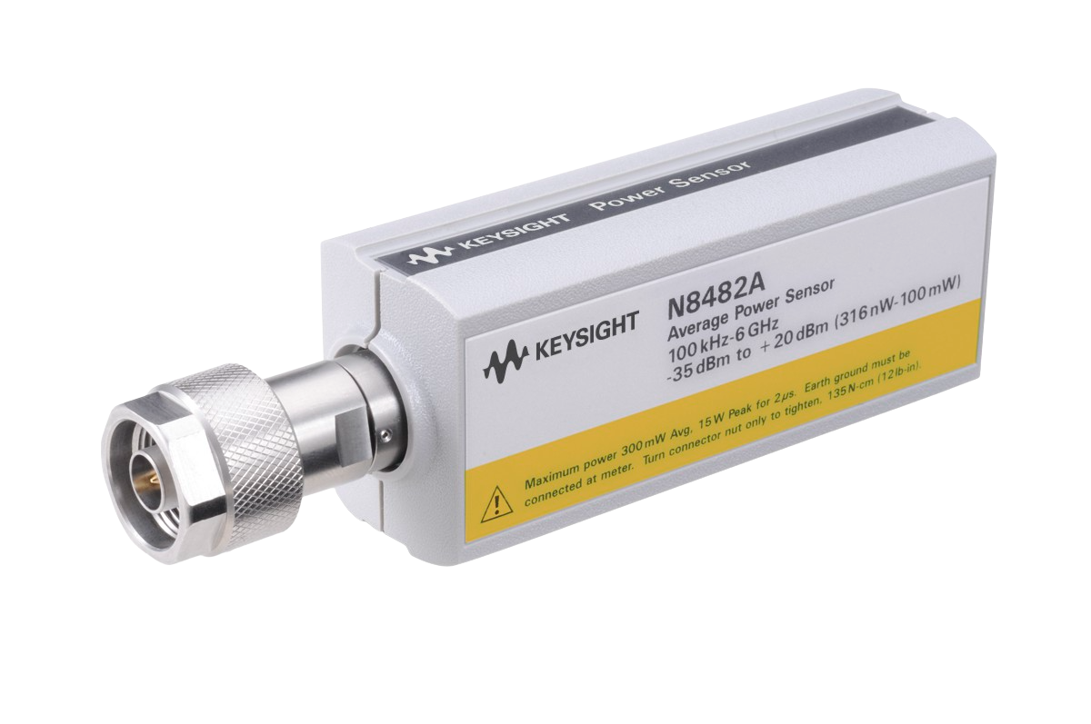
N8488A Standard N8488A model with
EEPROM feature 10 MHz to 67 GHz
–35 to +20 dBm
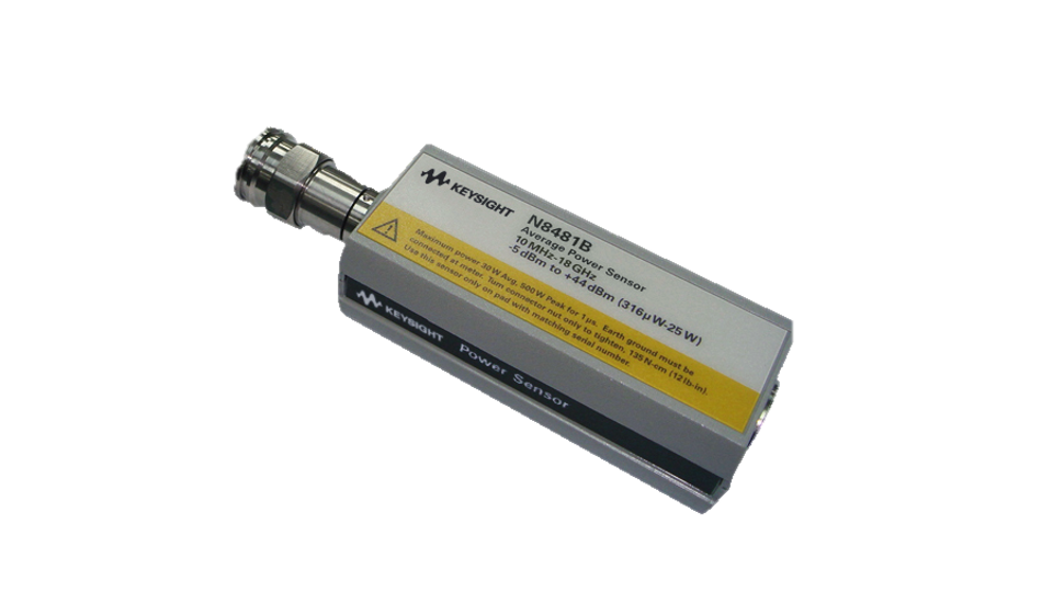
N8481B Standard N8481B model with
EEPROM feature 10 MHz to 18 GHz
–5 to +44 dBm
N8482B Standard N8482B model with
EEPROM feature 100 kHz to 6 GHz
–5 to +44 dBm
N8481H Standard N8481H model with
EEPROM feature 10 MHz to 18 GHz
–15 to +35 dBm
N8482H Standard N8482H model with
EEPROM feature 100 kHz to 6 GHz
–15 to +35 dBm
适用型号 N8486AR 标配 N8486AR 型号
with EEPROM feature 26.5 to 40 GHz
–35 to +20 dBm
适用型号 N8486AQ 标配 N8486AQ 型号
with EEPROM feature 33 to 50 GHz
–35 to +20 dBm
条件:Option CFT N8480 sensor without the calibration factor table stored in the EEPROM.
Calibration factor data is provided on the label attached to the power sensor
N8485A-033 N8485A model with EEPROM feature with extended frequency range,
10 MHz to 33 GHz
Certificate of Calibration
条件:please contact your local Keysight office. The complete list is available at:
This information is subject to change without notice. © Keysight Technologies, 2018 - 2026, Published in USA, January 6, 20 26, 5989
-9333EN
For more information on Keysight Technologies’ products, applications or services,
Option
100 Type-N (male) connector for N8481A, N8482A, N8481B, N8482B
3.5 mm (male) connector for N8485A
2.4 mm (male) connector for N8487A
1.85 mm (male) connector for N8488A
Waveguide connector for N8486AR & N8486AQ
Option
200 APC-7 (male) connector for N8481A only
Cables Description 11730A For EPM Series power meters: 1.5 m (5 ft), grey 11730B For EPM Series power meters: 3 m (10 ft), grey 11730C For EPM Series power meters
6.1 m (20 ft), grey
11730D For EPM Series power meters
15.2 m (50 ft), grey
11730E For EPM Series power meters
30.5 m (100 ft), grey
11730F 1 For EPM Series power meters
61 m (200 ft), grey
*Operates up to 45 °C
E9288A For EPM and EPM-P Series power meters
1.5 m (5 ft), blue
E9288B For EPM and EPM-P Series power meters
3 m (10 ft), blue
E9288C For EPM and EPM-P Series power meters
10 m (31 ft), blue
N1917A For P-Series power meters
1.5 m (5 ft)
N1917B For P-Series power meters
3 m (10 ft)
N1917C For P-Series power meters
10 m (31 ft)
条件:1. Only applicable for E4418/19B power meters .
Option 1A7 ISO
17025 calibration with test data
Option A6J ANSI Z540 calibration with test data
以上指标摘自厂家官方数据手册,完整定义、测试条件与保证值口径以手册为准。完整指标、测试条件与定义口径请见产品页「软件和手册 | 白皮书」栏目中的官方数据手册。
是德科技 | KEYSIGHT · onetest 仪器资源库


 客服








 粤公网安备44030902003758