是德科技 | KEYSIGHT
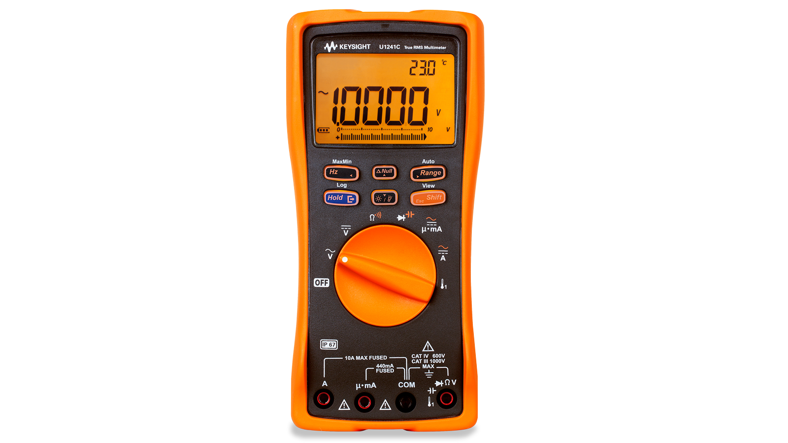
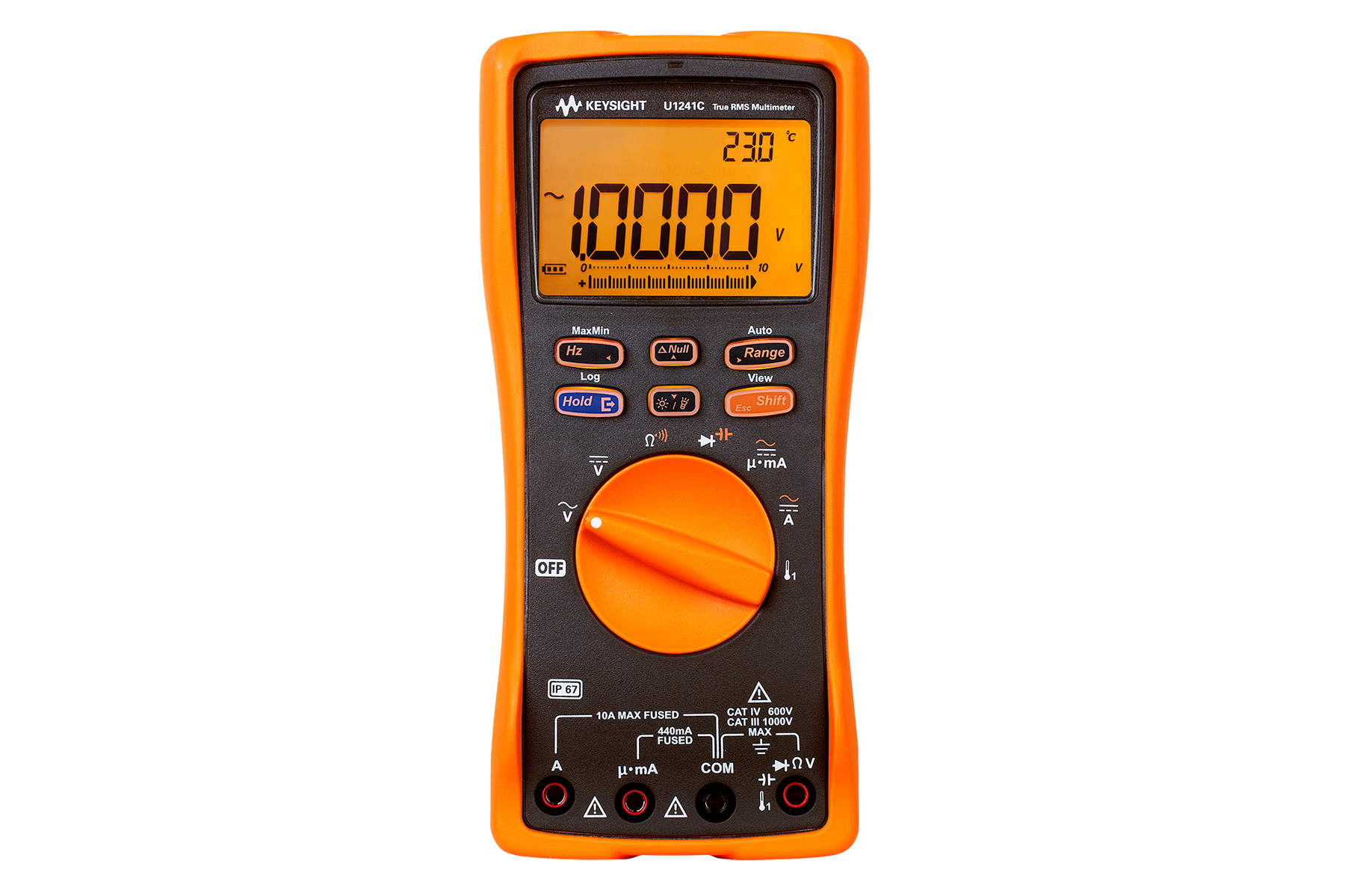
U1241C 万用表 详细指标
Make trustworthy measurements in harsh working environments
General specifications U1240C
Display 4 ½-digit Liquid Crystal Display (LCD) with maximum reading of
11,000-count
Automatic polarity indication
Power consumption
530 mVA maximum with backlight and flashlight.
Battery type 4x 1.5 V AA alkaline batteries (ANSI/NEDA
24A or IEC LR03), or
4x 1.5 V AA zinc chloride batteries (ANSI/NEDA
24D or IEC R03), or
4x 1.5 V AA lithium batteries (ANSI/NEDA
24-LF or IEC FR03)
Battery life 400 hours typical based on new alkaline batteries for DC voltage measurement
Connectivity Infrared (IR) port, connect with IR-USB cable
Fuse 10 x 35 mm, 440 mA / 1000 V
10 kA minimum fast-acting fuse
10 x 38 mm, 11 A / 1000 V
20 kA minimum fast-acting fuse
Operating environment Full accuracy from –20 °C to 55 °C; and up to 80% R.H. for temperature up to 30 °C decreasing
linearly to 50% R.H. at 55 °C
条件:Electromagnetic Compatibility (EMC) Refer to Declaration of Conformity for the latest revisions of regulatory compliance at:
electromagnetic phenomena, some recoverable degradation of performance may occur.
Specification assumptions 1. Accuracy is given as ± (% of reading + counts of least significant digit) at 23 °C ±5 °C, with relative humidity less than 80% R.H. 2. Accuracy is specified for 1- year after calibration, at operating temperature of room temperature. Multiply 1.5 times
of the accuracy for 2- year after calibration, example ± (1.5 x% of reading + 1.5 x counts of least significant digit).
3. AC V/mV and AC µA/mA/A specifications are AC coupled.
4. True RMS measurement is valid from 5% of range to 100% of range.
5. For non- sinusoidal waveforms, add (0.5% of reading +0.3% of full scale) typically
6. Crest factor ≤ 3 at full -scale and decrease reciprocally for overange as 3× Full Scale/Input; except for the 100 mV,
7. After Z LOW voltage measurement, wait for at least 20 minutes to cool down thermal impact before making next
Altitude up to 3000 meters
Storage compliance –40 °C to 70 °C
0 to 80% R. H. (with battery removed)
Safety compliance Refer to Declaration of Conformity for the latest revisions of regulatory compliance at
Measurement category CAT III 1000 V / CAT IV
600 V
Commercial limits compliance with EN61326-1
Influence of radiated immunity: In RF electromagnetic fields of 3 V/M
DC voltage measurement typical accuracy: 100 mV & 600 mV range
±0.1% of range
DC current measurement typical accuracy: 1000 uA & 10 mA range; ±0.3% of range 10 A range
±0.7% of range
Note: If used in close proximity to an RF transmitter or when subjected to continuously present
Ingress protection rating IP-67, protected against dust and the effect of immersion between
15 cm and 1 m
Temperature coefficient 0.05 x (specified accuracy)/°C (from
–20 °C to 18 °C or 28 °C to 55 °C)
Common Mode Rejection Ratio (CMRR) > 120 dB at DC, 50/60 Hz
±0.1% (1 kΩ unbalanced)
Normal Mode Rejection Ratio (NMRR) > 60 dB at 50/60 Hz
±0.1%
Dimensions (H x W x D) 198 x 96 x
57 mm
Weight
545 grams (with batteries)
Warranty Three years for main unit. Three months for standard shipped accessories
Calibration cycle One year, or; Two years (with
1.5 times of one year specification)
600 mV and 1000 V ranges, where these ranges have crest factor ≤
1.5 at full scale and decrease reciprocally for
overange as 1.5× Full Scale/Input. – Specification is based on
5 times/second of data refresh rate
measurement. 8. CMRR and NMRR are based on
5 times/second of data refresh rate
二、U1240C Series DC Specifications
Function Range Resolution Accuracy ± (% of reading + counts of least significant digit) Test current / burden voltage
Voltage 100 mV1,3 0.01 mV 0.09% + 2 — 600 mV1,3 0.1 mV 0.09% + 2 — 1000 mV4 0.1 mV 0.09% +
2 —
ZLOW2,4
(applicable to 1000 V range) 0.1 V 1% +
4 —
Current5
1000 µA3 0.1 µA 0.1% + 2
0.032 V (30 Ω)
10 mA3 0.001 mA 0.1% + 2
0.32 V (30 Ω)
100 mA1,3 0.01 mA 0.2% + 2
0.2 V (0.5 Ω)
600 mA1,3 0.1 mA 0.2% + 2
0.88 V (0.5 Ω)
10 A2,4 0.001 A 0.3% + 5
0.5 V (0.01 Ω)
Diode test — 0.001 V 0.5% + 10 <
1.6 mA
Function Range Resolution Accuracy ± (% of reading + counts of least significant digit) Continuity threshold
Resistance / audible continuity 100 Ω3,4,7 0.01 Ω 0.2% + 5 28
±10 Ω
1000 Ω4 0.1 Ω 0.2% + 2 28
±10 Ω
10 kΩ 0.001 kΩ 0.2% + 2 0.151
±0.05 kΩ
100 kΩ 0.01 kΩ 0.2% + 2 1.38
±0.5 kΩ
1000 kΩ 0.1 kΩ 0.2% + 2 13.8
±4.3 kΩ
10 MΩ5 0.001 MΩ 0.8% + 2 0.12
±0.04 MΩ
100 MΩ5,6 0.01 MΩ 1.5% + 3 (<
50 MΩ)
3.0% + 3 (> 50 MΩ) 0.12
±0.04 MΩ
Specification assumptions
条件:A. Notes for voltage specification. 1. 100 mV and 600 mV range available on Temperature T1 terminal. The accuracy is specified for 10 MΩ (nominal) input impedance. The accuracy is specified after NULL function is used to zero out thermal effect (by shorting test leads on a flat surface or a null value circuit).
2. Only available in U1242C only. 1.8 kΩ nominal input impedance for Z LOW mode.
3. Overload protection for 100 mV and 600 mV ranges: 1000 V rms for circuits < 0.3 A short circuit
use the NULL function to zero- out thermal effect with open test lead before measuring the signal.
2. Current can be measured up to 10 A continuously. Maximum of 30 seconds for measuring current
kA minimum fast -acting fuse. 5. Ensure good ventilation and no heat element close to the meter.
C. Notes for diode test specification 1. Overload protection: 1000 V rms for circuits < 0.3 A short circuit current. 2. Built -in buzzer sounds when reading is below 0.05 V approximately, and single tone for normal forward- biased diode or semiconductor junction as 0.3 V ≤ reading ≤ 0.8 V.
3. The maximum threshold voltage display is less than +2 V.
D. Notes for resistance/audible Continuity specification 1. Maximum open voltage: < +2.4 V 2. Built -in buzzer sounds as transient when resistance less than 28 ±10 Ω. It may capture the intermittent for longer than 1 ms.
3. 100 Ω range is for U1242C only
4. The accuracy is specified after Math Null, which is used to subtract the test lead resistance and
good ventilation and no heat element close to the meter . 5. For 10 MΩ and 100 MΩ ranges, the R.H. is specified for < 60% at 30 °C. 6. For 100 MΩ range: temperature coefficient is 0.1 x (specified accuracy) /°C. 7. Resistance range 100 Ω is typical characteristic.
current. 4. Overload protection
1000 V rms .
B. Notes for current specification 1. Current can be measured up to 440 mA continuously. Maximum of 20 hours for measuring current more than 440 mA and up to 600 mA. 100 mA and 600 mA ranges have thermal effect of 0.35 µA/mA to be offset after current applied to these ranges. Cool down the meter for at least
6
seconds if 100 mA was applied, and at least 3 minutes if
600 mA was applied; or alternatively
more than 10 A to 20 A, add 0.3% to specified accuracy. The multimeter needs to be cool down
after measuring current that is more than
10 A. Cool down the meter for twice the duration of the
measured time and use NULL function to zero- out thermal effect before proceeding with lower
current measurement. 3. 1000 µA to 600 mA ranges (connection with mA terminal) overload protection by 10 x 35 mm, 440 mA/1000 V, and 10 kA minimum fast -acting fuse. 4. 10 A ranges (connection with A terminal) overload protection by 10 x 38 mm, 11 A / 1000 V
20
the thermal effect (by shorting the test leads tips on a flat surface or a null value circuit). Ensure
条件:Notes: 1. Overload protection: 1000 Vrms. 2. 100 mV and 600 mV range available on Temperature T1 terminal. The accuracy is specified for 10 MΩ (nominal) input impedance. The accuracy is specified after NULL function is used to zero out thermal effect (by shorting test leads on a flat surface or a null value
circuit). 3. Only available in U1242C only. 1.8 kΩ nominal input impedance for ZLOW mode. 4. The input signal is lower than the product of 20,000,000 V x Hz.
Accuracy ± (% of reading + counts of least significant digit)
40 Hz to 1 kHz (True RMS)
1 kHz to 2 kHz (Averaging sense)6
AC voltage1,4
True RMS 100 mV2 0.01 mV 1.0% + 3 1.5% + 3 600 mV2 0.1 mV 1.0% + 3 1.5% + 3 1000 mV 0.1 mV 1.0% + 3 1.5% +
3
10 V 0.001 V 1.0% + 3 1.5% +
3
100 V 0.01 V 1.0% + 3 1.5% +
3
1000 V 0.1 V 1.0% + 3 1.5% +
3
ZLOW3
(applicable to 1000 V range) 0.1 V 2.0% +
4 N/A
AC voltage1,4
Averaging sense 100 mV2 0.01 mV 1.0% + 5 1.5% + 5 600 mV2 0.1 mV 1.0% + 5 1.5% + 5 1000 mV 0.1 mV 1.0% + 5 1.5% +
5
10 V 0.001 V 1.0% + 5 1.5% +
5
100 V 0.01 V 1.0% + 5 1.5% +
5
1000 V 0.1 V 1.0% + 5 1.5% +
5
条件:to zero-out thermal effect with open test lead before measuring the signal.
2. Current can be measured up to 10 A continuously. Maximum of 30 seconds for measuring current more than 10 A to 20 A, add 0.3% to
measurement. 3. 1000 µA to 1000 mA ranges (connection with mA terminal) overload protection by 10 x 35 mm, 440 mA / 1000 V, 10 kA minimum fast- acting fuse. 4. 10 A ranges (connection with A terminal) overload protection by 10 x 38 mm, 11 A / 1000 V, 20 kA minimum fast-acting fuse.
5. Ensure good ventilation and no heat element close to the meter.
6. The averaging sense is calibrated for sine wave only. Add additional 0.05 counts /°C to accuracy from -20 °C to 18°C or –28 °C to 55
Accuracy ± (% of reading + counts of least significant digit)
40 Hz to 1 kHz (True RMS)
1 kHz to 2 kHz (Averaging sense)6
AC current5
1000 µA3 0.1 µA 1.0% + 3 1.2% +
5
10 mA3 0.001 mA 1.0% + 3 1.2% +
5
100 mA3 0.01 mA 1.0% + 3 1.2% +
5
1000 mA1,3 0.1 mA 1.0% + 3 1.2% +
5
10 A2,4 0.001 A 1.2% + 54 1.2% +
5
Notes: 1. Current can be measured up to 440 mA continuously. Maximum of 20 hours for measuring current more than 440 mA and up to 600 mA. 100 mA and 600 mA ranges have thermal effect of 0.35 µA/mA to be offset after current applied to these ranges. Cool down the meter for at least 6 seconds if 100 mA was applied, and at least 3 minutes if
600 mA was applied; or alternatively use the NULL function
specified accuracy. The multimeter needs to be cool down after measuring current that is more than
10 A. Cool down the meter for
twice the duration of the measured time and use NULL function to zero-out thermal effect before proceeding with lower current
条件:hazard. 4. The temperature calculation is specified according to the safety standards of EN/IEC-60548-1 and NIST 175. 5. Only for U1242C.
Thermocouple type Range Resolution Accuracy ± (% of reading + as specified below)
K
–200°C to 1372°C 0.1°C 1% +
1°C
–328°F to 2502°F 0.1°F 1% + J5
1.8°F
–210°C to 1200°C 0.1°C 1% +
1°C
–346°F to 2192°F 0.1°F 1% +
1.8°F
Notes: 1. The specification above is specified after 60 minutes of warm-up time. 2. The accuracy does not include the tolerance of the thermocouple probe. 3. Do not allow the temperature sensor to contact a surface hat is energized above
30 Vrms or 60 V DC. Such voltages pose a shock
条件:Notes: 1. Overload protection: 1000 Vrms for short circuits with < 0.3 A current. 2. The accuracy for all ranges is specified based on a film capacitor or better, and after the Null function is used to subtract the test lead resistance and thermal effect (by opening the test leads).
3. The maximum display is 12000 counts selectable.
Range Resolution Accuracy ± (% of reading + counts of least significant digit)
条件:Note: 1. The frequency measurement is susceptible to error when measuring low-voltage, low-frequency signals. Shielding inputs from external noise pickup is critical for minimizing measurement errors. Turning on LPF (low pass filter) may help to filter out the noise and achieve a stable reading.
Range Resolution Accuracy ± (% of reading + counts of least significant digit) Minimum input
frequency 100.00 Hz 0.01 Hz 0.02% + 11 0.5 Hz 1000.0 Hz 0.1 Hz 0.02% +
1
10.000 kHz 0.001 kHz 0.02% +
1
100.00 kHz 0.01 kHz 0.02% +
1
1000.0 kHz 0.001 kHz 0.02% +
1
10.000 MHz 0.001 MHz 0.02% + 1, <
1 MHz
U1240C Series sensitivity for voltage measurement
输入范围最小值灵敏度 (RMS sine wave)
Maximum input1 for
specified accuracy 0.5 Hz to 20 kHz 20 kHz to 50 kHz
50 kHz to 100 kHz
100 mV2 15 mV 7.2 mV
15 mV
600 mV2 15 mV 7.2 mV
15 mV
1000 mV 125 mV 60 mV
125 mV
U1240C Series sensitivity for current measurement
输入范围最小值灵敏度 (RMS sine wave)
条件:Notes: 1. Refer to ‘AC specification’ for specified accuracy of maximum input. 2. 100 mV and 600 mV range available on Temperature T1 terminal.
Maximum input1 for specified accuracy 0.5 Hz to 20 kHz
20 kHz to 30 kHz
10 A N/A 1.15 A (<
10 kHz)
U1240C Series harmonic ratio (U1242C only)
Range Frequency Voltage 0.0% to 99.9% 40 Hz to 1 kHz
100 mVAC to 1000 VAC
U1240C Series multimeter data refresh rate
Function Slow (times/second) Fast (times/second)
Capacitance 0.8 (<
1000 μF) —
Frequency 1 (>
10 Hz) —
条件:Liquid Crystal Display (LCD) with maximum reading of 11,000 counts. Automatic polarity indication.
Safety & EMC compliance Refer to Declaration of Conformity for the latest revisions of regulatory compliance at:
electromagnetic phenomena, some recoverable degradation of performance may occur.
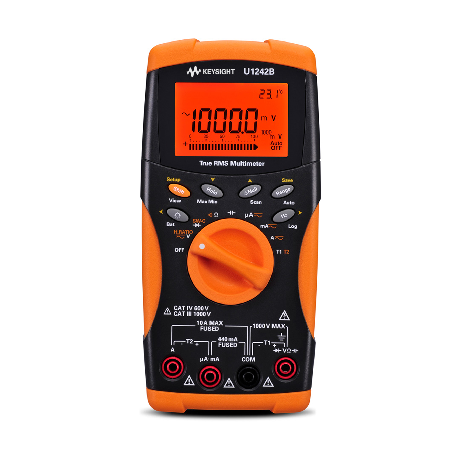
General specifications U1240B
Display Dual display (secondary display is intended for temperature function display only) consists of 4-digit
Power consumption
0.22 VA maximum
Battery type and life Four single standard 1.5 V AAA batteries (Alkaline or Zinc Chloride type)
300 hours typical
Operating environment Full accuracy at –10 to 55 °C; and to 80% RH for temperatures up to 30 °C, decreasing linearly to
50% RH at 55 °C
0 – 2000 meters per IEC 61010-1 3rd edition CAT III
1000 V/CAT IV
600 V IEC 61010-1
3rd edition
Storage compliance
–20 to 70°C
Measurement category CAT III 1000 V/CAT IV 600 V Overvoltage Protection, Pollution Degree
2
Commercial limits compliance with EN61326-1
Influence of radiated immunity: In RF electromagnetic fields of 3 V/M
DC voltage measurement typical accuracy: 1000 mV to 1000 V range
±0.2% of range
DC current measurement typical accuracy: 1000 uA & 10000uA range; ±0.7% of range 100 mA range; ±0.22% of range 440 mA range
±0.5% of range
10 A range
±0.11% of range
Note: If used in close proximity to an RF transmitter or when subjected to continuously present
Common mode rejection ratio (CMRR) > 90 dB at DC, 50/60 Hz
±0.1% (1 kΩ unbalanced)
Normal mode rejection ratio (NMRR) > 60 dB at 50/60 Hz
±0.1%
Crest factor Crest factor ≤ 3 at full-scale and decrease reciprocally for overange as
3× Full Scale/Input; except
for the 1000 V range, where this range has crest factor ≤
1.5 at full scale and decrease reciprocally
for overange as
1.5× Full Scale/Input.
Temperature coefficient 0.1 × (specified accuracy)/°C (from
–10 to 18 °C or 28 to 55 °C)
Shock and vibration Tested to IEC/EN
60068-2
Dimensions (H x W x D) 193.8 x 92.2 x
58.0 mm
Weight
450 g with batteries
400 g without batteries
以上指标摘自厂家官方数据手册,完整定义、测试条件与保证值口径以手册为准。完整指标、测试条件与定义口径请见产品页「软件和手册 | 白皮书」栏目中的官方数据手册。
是德科技 | KEYSIGHT · onetest 仪器资源库


 客服







 粤公网安备44030902003758