

 客服




输出频率范围:1 MHz 至 3.9 GHz
残余相位噪声: < -107 dBc/Hz @ 10 kHz, 1 GHz
输出电平: -100 dBm 至 17 dBm
LO泄漏: < 90 dBc
动态范围 > 150 dBc
其他:内部 IF 正弦波发生器
ONETEST 欢迎您
厂商登录 | 入驻
登录 | 注册 购物车 微信公众号厂商登录
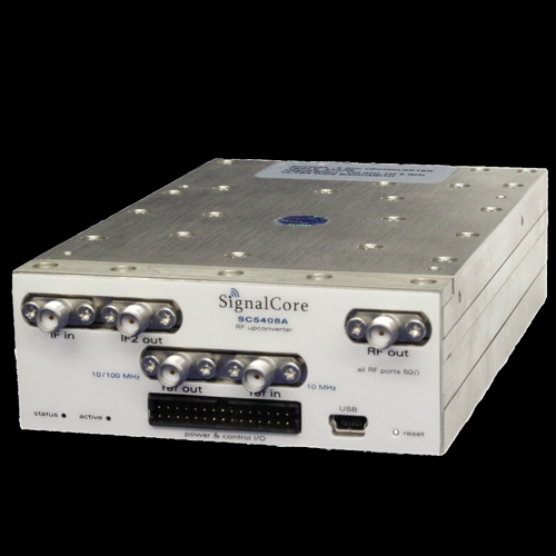
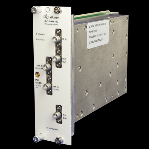
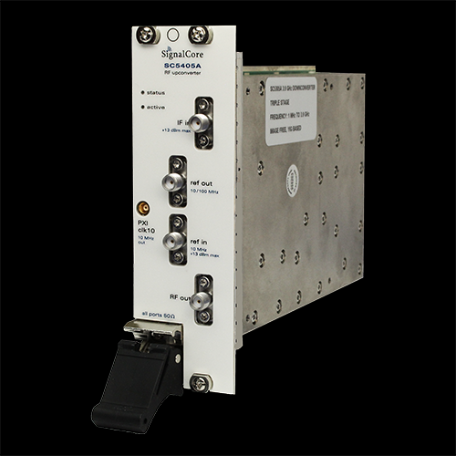
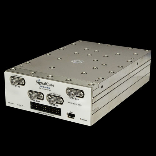
输出频率范围:1 MHz 至 3.9 GHz
残余相位噪声: < -107 dBc/Hz @ 10 kHz, 1 GHz
输出电平: -100 dBm 至 17 dBm
LO泄漏: < 90 dBc
动态范围 > 150 dBc
其他:内部 IF 正弦波发生器
SC5406B 1MHz至3.9GHz模块式射频上变频器|SignalCore
SC5405A 和 SC5406B 是三级、高动态范围、超外差上变频器。这两款模块设计用于将低频宽带中频信号转换为较高的射频信号,具有可与直接变频器件相媲美的三阶线性度和噪声性能,但没有固有的镜像和带内LO泄漏。当与SignalCore下变频器配对时,该对可以形成一个频率重新分配器,该频率重新分配器将接收一个频段上的信息,并在另一个频段上传输相同的信息。通过附加功能,SC5405A和SC5406B均可配置为1 MHz至3.9 GHz正弦音发生器。
每个模块都提供了完整的实现说明、GUI、驱动程序软件和示例代码。
Spectral Specifications
RF output range 1 ................................................................................................................................. 1 MHz to 3.9 GHz
IF input center frequency .................................................................................................................................. 70 MHz
IF input polarity 2 .................................................................................................................... Non inverted/Inverted
IF bandwidth
3 dB .............................................................................................................................................................. > 18 MHz
6 dB ............................................................................................................................................................... 20 MHz
RF tuning
Frequency step resolution 3 ........................................................................................................................ 1 Hz
Lock and settling times 4 .............................................................................................................................. 1 ms
Frequency reference 5
Technology ............................................................................... Temperature compensated crystal oscillator
Accuracy ................................ ± [(aging x last adjustment time lapse) + temp stability + cal accuracy]
Initial calibration accuracy ..................................................................................................................... ±0.05 ppm
Temperature stability 6
20 °C to 30 °C ........................................................................................................................................ ±0.25 ppm
0 °C to 55 °C .............................................................................................................................................. ±1.0 ppm
Aging .......................................................................................................................... ±1 ppm for first year @ 25 °C
Frequency accuracy 7.......................................± (frequency reference accuracy * RF input frequency) Hz
| Sideband phase noise(dBc/Hz) ⁸ | ||||
| RF Frequency | ||||
| Offset | 100 MHz | 1000 MHz | 2000 MHz | 3500 MHz |
| 100 Hz | -88 | -87 | -85 | -83 |
| 1 kHz | -100 | -99 | -98 | -97 |
| 10 kHz | -108 | -107 | -106 | -105 |
| 100 kHz | -119 | -118 | -117 | -115 |
| 1 MHz | -143 | -142 | -142 | -141 |
| 10 MHz | -150 | -149 | -149 | -148 |
LO related sideband spurious signals 10
< 200 kHz ...................................................................................................................................................< -75 dBc
> 200 kHz ...................................................................................................................................................< -80 dBc
Amplitude Specifications
Output range
0 dBm input IF signal 11........................................................................................-110 dBm to +16 dBm typical
Attenuation range
RF ................................................................................................................................................... 0 to 60 in 1 dB steps
IF 12 ................................................................................................................................................ 0 to 90 in 1 dB steps
Output voltage standing wave ratio (VSWR) (3 dB final RF attenuation)
10 MHz to 2.4 GHz .................................................................................................................................................. < 1.8
2.5 GHz to 3.6 GHz .................................................................................................................................................. < 2.5
Conversion gain 13
< 2000 MHz ............................................................................................................................................. 25 dB typical
> 2000 MHz............................................................................................................................................... 20 dB typical
RF amplitude accuracy (15 °C to 35 °C ambient)
RF gain response flatness (uncorrected)14 ................................................................................. 18 dB typical
RF gain flatness response (corrected15) ................................................................................................ ±0.75 dB
Absolute gain accuracy (corrected15) .................................................................... ±0.8 dB (±0.5 dB typical)
IF Amplitude accuracy (15 °C to 35 °C ambient)
IF in-band response flatness (uncorrected) ....................................................................... 2 dB peak typical
IF in-band response (corrected15) 14 ........................................................................................................... ±0.2 dB
RF to IF group delay (80% of IF bandwidth)16 ........................................................................... 960 ns typical
IF phase linearity (80% of IF bandwidth) ..................................................................................... +/- 8 degrees
IF phase linearity deviation rate..................................................................................................< 2 degrees/MHz
Dynamic Range Specifications
Spurious response 17
Final IF - RF output frequency 18 .............................................................................................. < -65 dBc typical
IF leakage ......................................................................................................................................... < -100 dBc typical
LO leakage........................................................................................................................................ < -100 dBc typical
Other intermodulated spurs ...................................................................................................... < -75 dBc typical
| Output noise (dBm/Hz)(15 ℃to 35 ℃ ambient)19 | |||
| 100 MHz | 1000 MHz | 3600 MHz | |
| Optimized lineary setting 20 | -130 | -130 | -132 |
| Optimized noise setting 21 | -148 | -150 | -148 |
| Output third-order intermodulation (OIP3,dBm)22 | ||||
| 100 | MHz-1GHz | 1 GHz-2.5 GHz | 2.5 GHz-3.9 GHz | |
| Optimized for linearity and noise setting | 36 | [39] | 32 [36] | 31 [34] |
| Output second harmonic (dBc) | |||
| Frequency | <1500 MHz | 1.5 GHz-3.2 GHz | >3.2 GHz |
| Optimized linearity and noise setting | <-45 | <-40 | <-50 |
| Output compression point (dBm)23 | |||
| Frequency | 50 MHz-3.0 GHz | 3.0 GHz-3.8 GHz | 3.8 GHz-3.9 GHz |
| With 0 dBm at IF input | 18 | 16 | 9 |
Reference Input and Output Specifications
Reference output specifications
Center frequency 24 ...................................................................................................................... 10 MHz/100 MHz
Amplitude ................................................................................................................................................ 3 dBm typical
Waveform .................................................................................................................................................................... Sine
Impedance ............................................................................................................................................... 50 nominal
Coupling ........................................................................................................................................................................... AC
Connector type .......................................................................................................................................... SMA female
Frequency accuracy ................................................................................ See “Spectral Specifications” section
Reference input specifications
Center frequency .............................................................................................................................................. 10 MHz
Amplitude .................................................................................................................. -10 dBm min/ +13 dBm max
Phase-lock range ............................................................................................................................ ± 5 ppm (typical)
Impedance ............................................................................................................................................... 50 nominal
Coupling ........................................................................................................................................................................... AC
Connector type .......................................................................................................................................... SMA female
Port Specifications
IF input Input impedance ..................................................................................................................................................... 50
Coupling ........................................................................................................................................................................... AC
VSWR............................................................................................................................................................................. < 1.3
Connector type .......................................................................................................................................... SMA female
Input amplitude ..................................................................................................................................... +23 dBm max
RF output
Output impedance .................................................................................................................................................. 50
Coupling ........................................................................................................................................................................... AC
Connector type .......................................................................................................................................... SMA female
Output amplitude ................................................................................................................................... 20 dBm max
General Specifications
Environmental
Operating temperature 25................................................................................................................... 0 °C to +55 °C
Storage temperature ....................................................................................................................... -40 °C to +70 °C
Operating relative humidity ............................................................................. 10% to 90%, non-condensing
Storage relative humidity .................................................................................... 5% to 90%, non-condensing
Operating shock ...................................................................................... 30 g, half-sine pulse, 11 ms duration
Storage shock ........................................................................................... 50 g, half-sine pulse, 11 ms duration
Operating vibration ........................................................................................................ 5 Hz to 500 Hz, 0.31 grms
Storage vibration ............................................................................................................. 5 Hz to 500 Hz, 2.46 grms
Altitude .............................. 2,000 m maximum (maintaining 25 °C maximum ambient temperature)
Physical
Dimensions (W x H x D, max envelope) (SC5406B)................................................... 3.7” x 1.4” x 6.1”
Dimensions (W x H x D, max envelope) (SC5405A)............................................................... 2x3U slots
Weight................................................................................................................................................................2.6 lbs
Input voltage (SC5406B)..........................................................................................................................12 VDC
Power consumption ........................................................................................................................ 24 W typical
Communication interface .......................................................................................... USB and RS-232 / SPI
Safety ............................................................................................................. Designed to meet the requirements of:
IEC 61010-1, EN 61010-1, UL 61010-1, CSA 61010-1
Electromagnetic Compatibility (EMC) ......................................... Designed to meet the requirements of:
EN 61326-1 (IEC 61326-1): Class A emissions; Basic immunity 1, EN 55011 (CISPR 11) Group 1, Class A emissions, AS/NZS CISPR 11: Group 1, Class A emissions, FCC 47 CFR Part 15B: Class A emissions, ICES-001: Class A emissions
CE ............................................................................................................................................. Meets the requirements of:
........................................... 2006/95/EC; Electromagnetic Compatibility Directive (EMC Directive)
Warranty .................................................. 3 years parts and labor on defects in materials or workmanship
SignalCore 官方与全球渠道
原厂直购
• 原厂直购(SignalCore, Inc.)
5211 FM 972, Granger, TX 76530, USA
电话 +1 512 501 6000 / +1 512 501 6001
销售 sales@signalcore.com | 支持 support@signalcore.com
亚太技术支持 +86 188 1322 2971
美洲渠道
• Mexel Servicios Sa de Cv(Mexico)
Pedro Moreno 1677,Piso 4 Oficina 6,Colonia Americana,Guadalajara Jalisco,Mexico CP 44160
电话 +52 333 615 2703 / +52 333 584 0413
www.mexser.com.mx
• SignalCore, Inc.(USA & Canada)
5211 FM 972,Granger, TX 76530
电话 +1 512 501 6000 / +1 512 501 6001
邮箱 sales@signalcore.com / support@signalcore.com
www.signalcore.com
亚太渠道
• Scientific Devices Pty. Ltd.(Australia)
118 Atkinson Street,Oakleigh VIC 3166, Australia
电话 +61 3 9569 1366 / sales@scientific-devices.com.au
邮箱 sales@scientific-devices.com.au
www.scientific-devices.com.au
• C&K Technologies Inc.(Korea)
#707, 36, Kkonmaeul-ro,,Deogyang-gu, Goyang-si,,Gyeonggi-do, 10545, Republic of Korea
电话 +82 2 6414 2330 / +82 10 3739 9325 / +82 2 6499 2041
• Skywave System Corp.(Taiwan)
5F., No. 12, Ln. 538, Zhongzheng Rd.,Xindian District,New Taipei City 23141,,Taiwan (R.O.C.)
电话 +886 2 866 75288 / +886 2 866 75286
邮箱 ssct_sales@skywave.com.tw
www.ssct.com.tw
欧洲与中东渠道
• Atlantese(Croatia | Serbia | Hungary | Finland | Bulgaria | Poland | Czech Republic | Atlantese)
De Wanne 50,9521 DB Nieuw-Buinen,The Netherlands,Patrick Gardner
电话 +31 641 382 394 / mailbox@atlantese.com
邮箱 mailbox@atlantese.com
www.atlantese.com
• Milexia France SAS(France | Belgium)
Espace Technologique de Saint-Aubin,Bâtiment Mercury II,91190 Saint-Aubin,France
电话 +33 1 69 53 80 00
邮箱 sales-france@milexia.com
www.milexia.com/fr
• bq microwave(Germany | Austria | Switzerland)
Hohe Str. 23,71549 Auenwald,Deutschland
电话 +49 151 25290128 / info@bq-microwave.de
邮箱 info@bq-microwave.de
www.bq-microwave.de
• Nisko Technologies Ltd.(Israel)
9 HaPsagot St.,Building C, 5th floor,Petah Tikva 4951041, Israel
电话 +972 3 7530700 / +972 3 7530701
邮箱 gideon@nisko-tech.com
www.nisko-tech.com
• Milexia Italia SpA(Italy)
Via Sardegna 1, 20146,Milano, Italy
电话 +39 02 4817900
邮箱 info_italy@milexia.com
www.milexia.com/it
• Radiocomp, LLC(Russia)
Aviamotornaya str. 8a,Moscow, Russia 111024
电话 +7 495 957 7745 / +7 495 020 10 64
邮箱 sales@radiocomp.ru
radiocomp.net
• Milexia Ibérica, S.A.U.(Spain | Portugal)
Calle De Nanclares de Oca, 5-7,E2 Planta Jardin C1,28022 Madrid, Spain
电话 +34 917 216 630
邮箱 comercial@milexia.com
www.milexia.com/es/
• Sematron Italia(Turkey)
Viale Marx 153/2,00137 Roma (RM) Italia
电话 +39 06 8689 5015 / +39 06 8680 2253
邮箱 marco@sematronitalia.eu
www.sematronitalia.com
• Milexia UK(United Kingdom)
3 Hazelwood, Lime Tree Way,Chineham Park, Basingstoke,,Hampshire, RG24 8WZ,UK
电话 +44 (0)1256 812222
邮箱 sales-uk@milexia.com
www.milexia.com/uk
编号#型号#描述接口7100019-01SC5405A3.9 GHz 射频上变频器 PXI Express7100059-01SC5406B3.9 GHz 射频上变频器 USB-SPI接口7100059-02SC5406B3.9 GHz 射频上变频器 USB-RS232接口7100021-01SC540XXSinetone Generation 附加组件7100155-01数字 I/O 和电源电缆
包含在产品套件中7100155-02数字I/O和电源电缆,
带2.5mm x 5.5mm插头7100158-0112V 电源套件
0条提问
X
提问
X
回答
发表口碑

AI问答




 粤公网安备44030902003758