是德科技 | KEYSIGHT
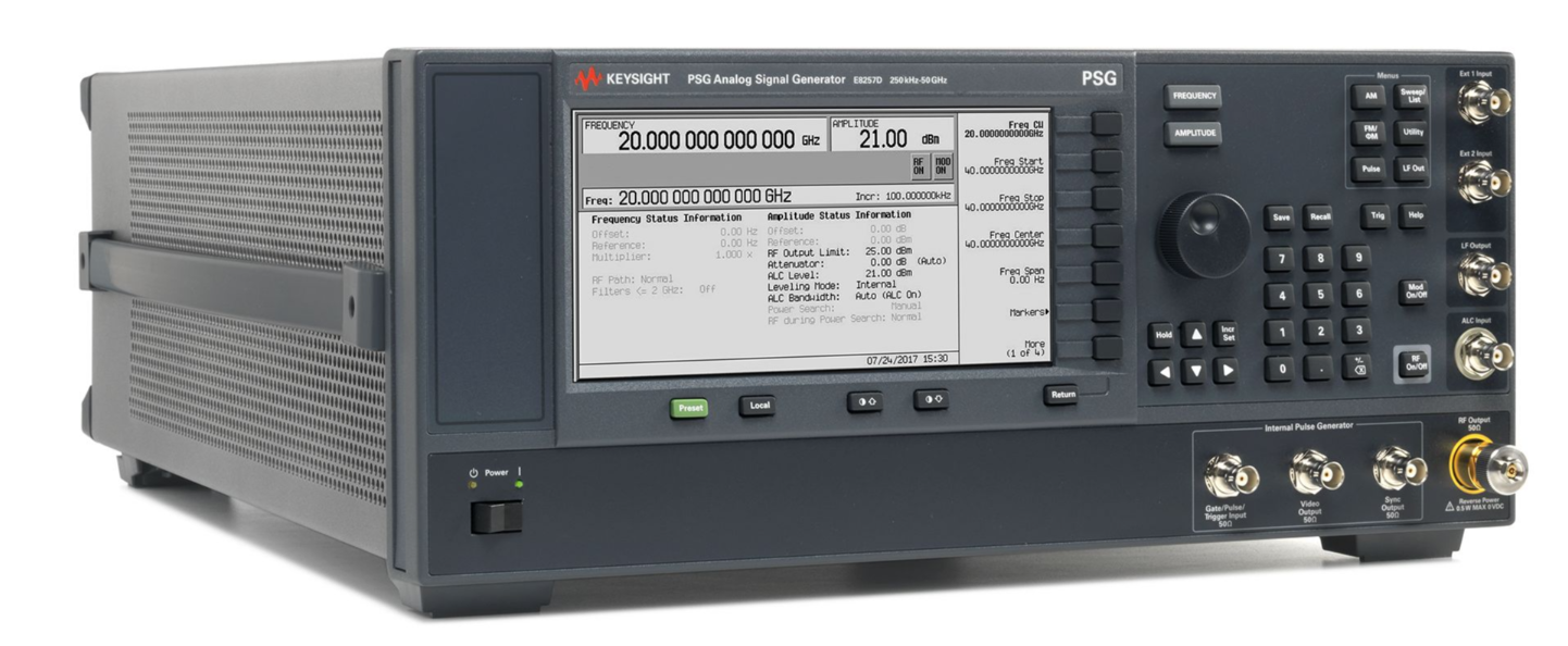
XG7系列E8257D 模拟信号发生器 100 kHz 至13/20/31.8/40/50/ 67 GHz 详细指标
模拟信号发生器
条件:Represents warranted performance for instruments with a current calibration.
Represents characteristic performance which is non-warranted. Describes performance that will be met
by a minimum of 80% of all products.
Represents characteristic performance which is non-warranted. Represents the value of a parameter that
is most likely to occur; the expected mean or mode of all instruments at room temperature (approximately
25 °C).
Represents characteristic performance which is non-warranted. Represents the value of a parameter
范围 Specified 范围 Tunable 范围
Option 513 250 kHz to 13 GHz
100 kHz to 13 GHz
Option 520 250 kHz to 20 GHz
100 kHz to 20 GHz
Option 521 1 10 MHz to 20 GHz
10 MHz to 20 GHz
Option 532 250 kHz to 31.8 GHz
100 kHz to 31.8 GHz
Option 540 250 kHz to 40 GHz
100 kHz to 40 GHz
Option 550 250 kHz to 50 GHz
100 kHz to 50 GHz
Option 567 250 kHz to 67 GHz
100 kHz to 70 GHz
条件:Phase offset Adjustable in nominal 0.1 ° increments
CW switching speed 3, 4
5 Standard Opt UNX Opt UNY
< 11 ms (typ) < 11 ms (typ) <
26 ms (typ)
< 7 ms (nom) < 7 ms (nom) <
22 ms (nom)
Frequency bands Frequency range N
6
2 > 250 to 500 MHz
1/16
3 > 500 MHz to 1 GHz
1/8
Accuracy ± [(time since last adjustment x aging rate) + temperature effects + line voltage effects + calibration accuracy]
Internal timebase reference oscillator (OCXO)
条件:1 For Option 521, performance is degraded below 500 MHz. Refer to specifications for more detail.
5 With Option 1EH low band harmonic filters off. With the 1EH filters turned on, add 4 ms.
< ± 2.5 ×10⁻¹⁰/day after
30 days
Initial achievable calibration accuracy < ± 4 x
10–8
Temperature effects (typ) < ± 4.5 x
10–9 from 0 to 55 °C
Line voltage effects (typ) < ± 2 ×10⁻¹⁰ for
± 10% change
2 In ramp sweep mode (Option 007), resolution is limited with narrow spans and slow sweep speeds. Refer to ramp sweep
specifications for more information . 3 Time from GPIB trigger to frequency within 0.1 ppm of final frequency above 250 MHz or within 100 Hz below 250 MHz. CW switching speed to within 0.05% of final frequency is ≥ 5 ms (nom). 4 Add 12 ms (typical) when switching from greater than 3.2 GHz to less than 3.2 GHz. Option HY2 switching speed is
30 ms (nom)
for 250 kHz to 3.2 GHz and 40 ms (nom) for >
3.2 GHz.
6 N is a factor used to help define certain specifications within the document.
7 Not verified by Keysight N7800A TME Calibration and Adjustment Software. Daily aging rate may be verified as a supplementary
Amplitude > +4 dBm into
50 Ω load (typ)
Input impedance
50 Ω (nom)
Operating modes Step sweep of frequency or amplitude or both (start to stop)
List sweep of frequency or amplitude or both (arbitrary list)
频率扫描 Within instrument 频率范围
Amplitude sweep Within attenuator hold range (see “Output” section)
List sweep
2 to 1601 per table
Frequency 9 < 9 ms (typ) < 9 ms (typ) <
24 ms (typ)
Amplitude < 5 ms (typ) < 5 ms (typ) <
5 ms (typ)
8 To optimize phase noise use 5 dBm
± 2 dB.
9 19 ms (typ) when stepping from greater than 3.2 GHz to less than 3.2 GHz. Option HY2 switching speed is
30 ms (nom)
for 250 kHz to 3.2 GHz and 40 ms (nom) for >
3.2 GHz.
Ramp (analog) sweep (Option 007)
10
• Synthesized frequency sweep (start/stop), (center/span), (swept CW)
条件:Frequency accuracy ± 0.05% of span ± timebase (at 100 ms sweep time, for sweep spans less than maximum values given above).
° Alternates successive sweeps between current and stored states
Sweep span range Settable from minimum
11 to full range
Maximum sweep rate Start frequency Maximum sweep rate Max span for 100 ms sweep
250 kHz to < 0.5 GHz 25 MHz/ms
2.5 GHz
0.5 to < 1 GHz 50 MHz/ms
5 GHz
1 to < 2 GHz 100 MHz/ms
10 GHz
2 to < 3.2 GHz 200 MHz/ms
20 GHz
≥ 3.2 GHz 400 MHz/ms
40 GHz
Accuracy improves proportionally as sweep time increases
12
Sweep time (forward sweep, not including bandswitch and retrace intervals)
Manual mode Settable
10 ms to 200 seconds
Auto mode Set to minimum value determined by maximum sweep rate and 8757D setting
Triggering Auto, external, single, or GPIB
Markers
10 independent continuously variable frequency markers
显示 Z-axis intensity 或 RF 幅度脉冲
条件:alw ays be displayed correctly. 12 Typical accuracy for sweep times > 100 ms can be calculated from the equation: [(0.005% of span)/(sweep time in seconds)] ± timebase. Accuracy is not specified for sweep times < 100 ms. 13 For primary/secondary operation use Keysight part number 8120- 8806 primary/secondary interface cable.
frequency display, pass -through mode, and alternate sweep, do not function with PSG signal generators.
Functions M1 to center, M1/M2 to start/stop, marker delta
Two-tone (primary/secondary) measurements
13
Two PSGs can synchronously track each other, with independent control of start/stop frequencies
Network analyzer compatibility Compatible with Keysight 8757D scalar network analyzer. Also useable with Keysight
8757A/C/E scalar network
analyzers for making basic swept measurements.
14
10 During ramp sweep operation, AM, FM, phase modulation, and pulse modulation are usable but performance is not guaranteed.
11 Minimum settable sweep span is proportional to carrier frequency and sweep time. Actual sweep span may be slightly different
than desired setting for spans less than [0.00004% of carrier frequency or 140 Hz] x [sweep time in seconds]. Actual span wil l
14 GPIB system interface is not supported with 8757A/C/E, only with 8757D. As a result, some features of 8757A/C/E, such as
条件:With Option 1E1 step attenuator
16 With Option 1EH low -pass filters below 2 GHz switched off, unless otherwise specified.
typical from 0 to 15 °C. Maximum operating temperature of Option HY2 is 35 °C.
19 With Option 1EH low -pass filters below 2 GHz switched off. With filters on, this specification applies above 2 GHz.
20 With Option HY2 operating in SNR mode.
22 With Option 1EH low -pass filters below 2 GHz switched off, unless otherwise specified.
25 With Option 1EH low -pass filters below 2 GHz switched off. With filters on, this specification applies above 2 GHz.
27 With Option 1EH low -pass filters below 2 GHz switched off, unless otherwise specified.
29 With Option 1EH low -pass filters below 2 GHz switched off. With filters on, this specification applies above 2 GHz.
Options 513, 520, 521, 532, and 540
–135 dBm
Options 550 and 567
–110 dBm
Maximum output power (dBm)
15 Spec (Typ)
Frequency range 16 Standard Option 1EU Option 1E1 Options 1E1 + 1EU Option HY2
17
Low phase noise mode on 10 to 250 MHz (filters on) +11 +11 (+13) +11 +11 (+13) 1 to 250 MHz (filters off) 18 +15 +16 (+17) +15
+16 (+17)
Low phase noise mode off 10 to 250 MHz (filters on) +15 +15 (+17) +15
+15 (+17)
> 0.25 to 2 GHz (filters on) +15 +16 (+17) +15
+16 (+17)
250 kHz to 10 MHz +14 +14 (+17) +14
+14 (+17)
> 10 to < 60 MHz +15 +16 (+19) +15
+16 (+19)
60 to 400 MHz +15 +20 (+21) +15
+20 (+21)
> 0.4 to 3.2 GHz 19 +15 +21 (+23) +15
+21 (+23)
> 3.2 to 10 GHz +15 +22 (+23) +14
+21 (+22)
> 10 to 20 GHz +15 +21 (+23) +14
+19 (+21)
Option HY2 carrier frequency
20
250 kHz to < 1 MHz
+14 (+17)
1 MHz to < 10 MHz
+16 (+17)
> 0.25 to 2 GHz
+16 (+17)
> 2 to 3.2 GHz
+21 (+23)
> 3.2 to 10 GHz
+21 (+22)
> 10 GHz to 20 GHz
+19 (+21)
15 Maximum power specifications are warranted from 15 to 35 °C, and are typical from 0 to 15 °C. Maximum power over the
35 to
55 °C range typically degrades less than
2 dB.
17 Option HY2 requires ordering Option 1E1 +1EH
+1EU. Maximum power specifications are warranted from 15 to 35 °C and are
18 In this mode, harmonics are large and output power refers to the total power including harmonics.
Maximum output power (dBm)
21 continued Spec (Typ)
Frequency range 22 Standard Option 1EU Option 1E1 Options 1E1 +
1EU
Low phase noise mode on 10 to 250 MHz (filters on) +11 (+13) n/a +11 (+13) n/a 10 to 250 MHz (filters off) 24 +16 (+17) n/a
+16 (+17) n/a
Low phase noise mode off 10 to 250 MHz (filters on) +16 (+18) n/a
+16 (+18) n/a
> 0.25 to 2 GHz (filters on) +18 (+20) n/a
+18 (+20) n/a
10 to 250 MHz +19 (+21) n/a
+19 (+21) n/a
> 0.25 to 1 GHz +24 (+26) n/a
+24 (+26) n/a
> 1 to 6 GHz 25 +28 (+30) n/a
+28 (+30) n/a
> 6 to 14 GHz +28 (+30) n/a
+27 (+28) n/a
> 14 to 17.5 GHz +26 (+28) n/a
+25 (+27) n/a
> 17.5 to 20 GHz +24 (+27) n/a
+23 (+26) n/a
Option 532 and 540 Standard Option 1EU Option 1E1 Options 1E1 +
1EU
Low phase noise mode on 10 to 250 MHz (filters on) +10 +10 (+12) +10 +10 (+12) 1 to 250 MHz (filters off) 24 +11 +15 (+16) +11
+15 (+16)
Low phase noise mode off 10 to 250 MHz (filters on) +11 +14 (+16) +11
+14 (+16)
> 0.25 to 2 GHz (filters on) +11 +15 (+16) +11
+15 (+16)
250 kHz to 10 MHz +11 +13 (+16) +11
+13 (+16)
> 10 to < 60 MHz +11 +15 (+18) +11
+15 (+18)
60 to 400 MHz +11 +19 (+21) +11
+19 (+21)
> 0.4 to 3.2 GHz 25 +11 +20 (+22) +11
+20 (+22)
> 3.2 to 17 GHz +11 +19 (+21) +10
+17 (+20)
> 17 to 20 GHz +11 +18 (+20) +9
+18 (+20)
> 20 to 28 GHz +11 +19 (+20) +9
+18 (+20)
> 28 to 37 GHz +11 +16 (+18) +9
+15 (+17)
> 37 to 40 GHz +11 +14 (+17) +9
+12 (+16)
21 Maximum power specifications are warranted from 15 to 35 °C, and are typical from 0 to 15 °C. Maximum power over the
35 to
55 °C range typically degrades less than
2 dB.
23 Option 521 includes low -pass filters below
2 GHz as standard.
24 In this mode, harmonics are large and output power refers to the total power including harmonics.
Maximum output power (dBm)
26 continued Spec (Typ)
Frequency range 27 Standard Option 1EU Option 1E1 Options 1E1 +
1EU
Low phase noise mode on 10 to 250 MHz (filters on) +5 +9 (+11) +5 +9 (+11) 1 to 250 MHz (filters off) 28 +5 +14 (+16) +5
+14 (+16)
Low phase noise mode off 10 to 250 MHz (filters on) +5 +13 (+15) +5
+13 (+15)
> 0.25 to 2 GHz (filters on) +5 +14 (+15) +5
+14 (+15)
250 kHz to 10 MHz +5 +12 (+15) +5
+12 (+15)
> 10 to < 60 MHz +5 +14 (+17) +5
+14 (+17)
60 to 400 MHz +5 +18 (+20) +5
+18 (+20)
> 0.4 to 3.2 GHz 29 +5 +19 (+21) +5
+19 (+21)
> 3.2 to 15 GHz +5 +18 (+21) +4
+17 (+20)
> 15 to 30 GHz +5 +14 (+16) +3
+13 (+15)
> 30 to 65 GHz +5 +11 (+14) +3
+9 (+12)
> 65 to 67 GHz +5 +10 (+14) +3
+8 (+12)
> 67 to 70 GHz (+5) (+8) (+3) (+6)
26 Maximum power specifications are warranted from 15 to 35 °C, and are typical from 0 to 15 °C. Maximum power over the
35 to
55 °C range typically degrades less than
2 dB.
28 In this mode, harmonics are large and output power refers to the total power including harmonics.
条件:31 With attenuator in auto mode. Optimize S/N mode provides improved signal/noise performance and is included with Option 521
Step attenuator (Option 1E1)
30
Options 513, 520, 521, 532, and 540
0 dB and 5 dB to 115 dB in 10 dB steps
With Optimize S/N on 31
0 dB to 115 dB in 5 dB steps
Options 550 and 567
0 dB to 90 dB in 10 dB steps
30 The step attenuator provides coarse power attenuation to achieve low power levels. Fine power level adjustment is provided by
the ALC (automatic level control) within the attenuator hold range.
and Option 1EU models. Specs in the following sections (such as level accuracy, spectral purity, modulation, etc) are only
条件:Minimum From –20 dBm to maximum specified output power with step attenuator in 0 dB position.
Can be offset using Option
1E1 attenuator.
条件:33 To within 0.5 dB of final amplitude within one attenuator range. Also applies to Option 521 below 500 MHz with ALC on.
34 Specifications apply in CW and list/step sweep modes over the 15 to 35 ºC temperature range with the ALC on. Degradation
Option 521 below 500 MHz). In ramp sweep mode (with Option 007), specifications are typical. For instruments with Type- N
connectors (Option 1ED), specifications are degraded typically 0.2 dB above 18 GHz.
filters below 2 GHz are on. With Option 1EH low -pass filters below 2 GHz off, accuracy is typically ± 2 dB.
36 For Option 550 and 567, degrade level accuracy by 0.2 dB from 1.7 to 2 GHz when step attenuator is set to 0 dB or when
37 Nominal above +16 dBm from 10 MHz to 60 MHz.
38 With Option 521, specifications below 500 MHz are typical, and apply for a 50 Ω load with VSWR less than 1.4:1.
41 Specifications apply in CW and list/step sweep modes over the 15 to 35 ºC temperature range, with the ALC on and attenuator
10 dBm, is typically < 0.3 dB (except < 0.5 dB from 2 to 3.2 GHz and with Option 521 below 500 MHz). In ramp sweep mode
(with Option 007), specifications are typical. For instruments with type- N connectors (Option 1ED), specifications apply to
42 With Option 521, specifications below 500 MHz apply with step attenuator set to 5 dB or higher (requiring Attenuator Hold ON
above 8 dBm). With step attenuator set to 0 dB, refer to level accuracy specifications without Option 1E1.
ALC off < 10 ms (typ) (not including power search)
33
(dB) > 20 dBm 20 to > 16 dBm 16 to > 10 dBm 10 to > 0 dBm 0 to –10 dBm <
–10 to –20 dBm
Options 513, 520, 532, 540, 550
567
250 kHz to 2 GHz 35, 36 ± 0.8 ± 0.8 37 ± 0.6 ± 0.6 ± 0.6
± 1.2
> 2 to 20 GHz ± 1.0 ± 0.8 ± 0.8 ± 0.8 ± 0.8
± 1.2
> 20 to 40 GHz — ± 1.0 ± 1.0 ± 0.9 ± 0.9
± 1.3
> 40 to 50 GHz — — — ± 1.3 ± 0.9
± 1.2
> 50 to 67 GHz — — — ± 1.5 ± 1.0
± 1.2 (typ)
10 to < 500 MHz 35, 38 ± 1.9 (typ) ± 1.2 (typ) ± 1.2 (typ) ± 1.1 (typ) ± 1.2 (typ)
± 1.2 (typ)
0.5 to 20 GHz ± 1.0 39 ± 0.8 ± 0.8 ± 0.8 ± 0.9 ± 1.1
40
Level accuracy with step attenuator (Option 1E1)
41 (dB)
26 to > 20 dBm 20 to > 16 dBm 16 to > 10 dBm 10 to > 0 dBm 0 to –10 dBm < –10 to –70 dBm <
–70 to –90 dBm
Options 513, 520, 532, 540, 550
567
250 kHz to 2 GHz 35, 36 ± 1.0 ± 0.8 37 ± 0.6 ± 0.6 ± 0.6 ± 0.7
± 0.8
> 2 to 20 GHz ± 1.0 ± 0.8 ± 0.8 ± 0.8 ± 0.8 ± 0.9
± 1.0
> 20 to 40 GHz — ± 1.0 ± 1.0 ± 0.9 ± 0.9 ± 1.0
± 2.0
> 40 to 50 GHz — — — ± 1.3 ± 0.9 ± 1.5
± 2.5
> 50 to 67 GHz — — — ± 1.5 ± 1.0 ± 1.5 (typ)
± 2.5 (typ)
10 to < 500 MHz 35,42 ± 1.3 ± 0.8 ± 0.8 ± 0.7 ± 1.0
± 1.0
0.5 to 20 GHz ± 1.0 39 ± 0.8 ± 0.8 ± 0.8 ± 0.8 ± 1.1
± 1.1
32 To within 0.1 dB of final amplitude within one attenuator range. Does not apply to Option 521 below
500 MHz.
outside this temperature range, for power levels > -10 dBm is typically < 0.3 dB (except <
0.5 dB from 2 to 3.2 GHz and with
35 When Option UNX or UNY low phase noise mode is on, specifications below 250 MHz apply only when Option
1EH low -pass
Option
1E1 is not present.
hold off (normal operating mode). Degradation outside this temperature range, with attenuator hold on and ALC power levels > -
18 GHz only.
Temperature stability 0.02 dB/°C (typ)
43
Number of points
2 to 1601 points/table
Number of tables Up to 10,000, memory limited
通路 loss Arbitrary, within 衰减器范围
Entry modes Remote power meter
44, remote bus, manual (user edit/view)
Output impedance
50 Ω (nom)
条件:< 1.6:1 (typ) with Option 1E1 step attenuator set ≥ 5 dB
Options 513, 520, 532, 540, 550
567
250 kHz to 2 GHz < 1.4:1 (typ)
45
> 2 GHz to 20 GHz <
1.6:1 (typ)
> 20 GHz to 40 GHz <
1.8:1 (typ)
> 40 GHz to 67 GHz <
2.0:1 (typ)
10 to < 500 MHz < 6:1 (typ) without Option
1E1, or step attenuator set to 0 dB
0.5 to 20 GHz <
1.8:1 (typ)
Leveling modes Internal leveling, external detector leveling, millimeter source module, ALC off
Range –0.2 mV to –0.5 V (nom) (–36 dBm to +4 dBm using Keysight
33330D/E detector)
Bandwidth Selectable
0.1 to 100 kHz (nom) (Note: not intended for pulsed operation)
Maximum reverse power 1/2 Watt
0 VDC46
Adjustable RF output limit
Function Protects external devices by limiting maximum RF output. Operates in all leveling modes (internal, external, source module)
Range User-adjustable from +15 dBm to maximum output power
条件:Adjustment Can be locked to prevent accidental change 43 Options 550 and 567: 0.03dB/°C (typ) above 2 GHz. Option 521: 0.03 dB/°C (typ) below 500 MHz. 44 Compatible with Keysight EPM/EPM -P Series power meters. 45 For Options 550 and 567, SWR is 1.7:1 (typ) from 1.7 to 2.0 GHz when the step attenuator is set to 0 dB.
46 For Option 521, maximum reverse power is 1/2 watt when Option 1E1 step attenuator is set at or above 5 dB. When Option 1E1
+15 to +25 dBm
± 1 dB (typ)
> +25 dBm
± 1.5 dB (typ)
Response time
30 μsec (measured)
step attenuator = 0 dB, or for units without Option 1E1, maximum reverse power is 2 watts above 250 MHz, 1/2 watt below
250
条件:10 to < 60 MHz with Option 1EH filters on –45 dBc 48 –35 dBc 48, 49
10 to 250 MHz with Option HY2 in SNR mode and filters off –8 dBc (typ)
0.06 to 2 GHz with Option 1EH filters on 51 –55 dBc 48 –35 dBc 48, 49
> 0.25 to 2 GHz with Option HY2 in SNR mode and filters off – 25 dBc (typ)
With Option 1EH filters off –8 dBc (typ) –8 dBc (typ)
With Option 1EH filters on –55 dBc 52 –35 dBc
47 Specifications are typical for harmonics beyond specified frequency range (beyond 50 GHz for Option 567). Specifications are
with Option 1EH Low -pass Filters below 2 GHz off and Option UNX or UNY low phase noise mode off unless noted.
off. 49 Option 521 includes low -pass filters below 2 GHz as standard. 50 For serial number ≥ MY/SG6305XXXX, a t 250.0001 MHz, -24 dBc for options 513, 520, 532, 540, 550, 567 and -19 dBc for option 521.
Harmonics
47 (dBc at +10 dBm or maximum specified output power, whichever is lower)
Frequency Options 513, 520, 532, 540, 550, 567 Option
521
10 to < 60 MHz –28 dBc
–25 dBc
0.06 to 2 GHz 50 –30 dBc
–25 dBc
> 2 to 20 GHz –55 dBc
–35 dBc
> 20 to 67 GHz
–50 dBc (typ)
10 to 250 MHz, Option UNX or UNY low phase noise mode
48 Below 250 MHz in ramp sweep mode (Option 007), Option
1EH filters are always off. Refer to harmonic specification with filter s
51 For serial number ≥ MY/SG6305XXXX, at 250.0001 MHz, -49 dBc for options 513, 520, 532, 540, 550
567 and -29 dBc for
Sub-harmonics
53 (dBc at +10 dBm or maximum specified output power, whichever is lower)
250 kHz to 10 GHz None
> 10 GHz to 20 GHz <
–60 dBc
Non-harmonics 54, 55
56 (dBc at +10 dBm or maximum specified output power, whichever is lower)
Frequency Offsets >
3 kHz
条件:CW mode with Option UNX or UNY < N x 4 Hz (typ)
53 Sub- harmonics are defined as carrier freq*(x/y), where x and y are integers, and x is not an integer multiple of y. Specifications
are typical for sub- harmonics beyond specified frequency range. For Option 567, specifications are typical for carrier
54 Specifications are typical for spurs beyond specified frequency range (beyond 50 GHz for Option 567). Specifications apply for
CW mode, without modulation. In ramp sweep mode (Option 007), performance is typical for offsets > 1 MHz.
radio frequency EM fields in the range of 800 MHz - 5 GHz when tested per IEC 61000-4- 3.
Line-related (≤ 300 Hz) (typ) 250 kHz to 250 MHz –58 (–62 57) –58 (–62 57)
–58 (–55)
1 to 250 MHz 58 –80 (–88) –80 (–88)
–80 (–55)
> 250 MHz to 1 GHz –80 (–88) –80 (–88)
–80 (–55)
> 1 to 2 GHz –74 (–82) –74 (–82)
–80 (–55)
> 2 to 3.2 GHz –68 (–76) –68 (–76)
–76 (–55)
> 3.2 to 10 GHz –62 (–70) –62 (–70)
–70 (–50)
> 10 to 20 GHz –56 (–64) –56 (–64)
–64 (–45)
> 20 to 40 GHz –50 (–58) –50 (–58)
–58 (–39)
> 40 GHz –44 (–52) –44 (–52)
–52 (–37)
Residual FM (RMS
50 Hz to 15 kHz bandwidth)
CW mode < N x
6 Hz (typ)
Ramp sweep mode < N x
1 kHz (typ)
Broadband noise (CW mode at +10 dBm or maximum specified output power, whichever is lower, for offsets >
10 MHz)
10 MHz to 20 GHz (without Option 521) <
–148 dBc/Hz (typ)
10 MHz to 20 GHz (Option 521) <
–142 dBc/Hz (typ)
> 20 to 40 GHz <
–141 dBc/Hz (typ)
> 40 GHz <
–135 dBc/Hz (typ)
55 Excluding external mechanical vibration.
56 This product may have some performance loss (non- harmonics up to -45 dBc at 1 kHz offset) when exposed to 3 V/m ambient
57 For offsets >
10 kHz.
58 Option UNX or UNY low phase noise mode.
Standard carrier frequency SONET/SDH data rates RMS jitter bandwidth Unit intervals (μUI) Time (fs)
155 MHz 155 MB/s 100 Hz to 1.5 MHz 30
190
622 MHz 622 MB/s 1 kHz to 5 MHz 27
43
2.488 GHz 2488 MB/s 5 kHz to 20 MHz 84
34
9.953 GHz 9953 MB/s 10 kHz to 80 MHz 222
22
39.812 GHz 39812 MB/s 40 kHz to 320 MHz 804
21
Option UNX carrier frequency SONET/SDH data rates RMS jitter bandwidth Unit intervals (μUI) Time (fs)
155 MHz 155 MB/s 100 Hz to 1.5 MHz
47
622 MHz 622 MB/s 1 kHz to 5 MHz 27
43
2.488 GHz 2488 MB/s 5 kHz to 20 MHz 86
35
9.953 GHz 9953 MB/s 10 kHz to 80 MHz 197
20
39.812 GHz 39812 MB/s 40 kHz to 320 MHz 817
21
Option UNY carrier frequency SONET/SDH data rates RMS jitter bandwidth Unit intervals (μUI) Time (fs)
155 MHz 155 MB/s 100 Hz to 1.5 MHz
36
622 MHz 622 MB/s 1 kHz to 5 MHz 21
34
2.488 GHz 2488 MB/s 5 kHz to 20 MHz 53
21
9.953 GHz 9953 MB/s 10 kHz to 80 MHz 97
10
39.812 GHz 39812 MB/s 40 kHz to 320 MHz 415
10
59 Calculated from phase noise performance in CW mode only at +10 dBm. For other frequencies, data rates, or bandwidths,
please contact your sales representative
SSB phase noise (dBc/Hz) (CW) 60, 61
20 kHz offset from carrier
please contact your sales representative
| Frequency | Spec | Typical |
|---|
| 250 kHz to 250 MHz | –130 | –134 |
| > 250 to 500 MHz | –134 | –138 |
| > 500 MHz to 1 GHz | –130 | –134 |
| > 1 to 2 GHz | –124 | –128 |
| > 2 to 3.2 GHz | –120 | –124 |
| > 3.2 to 10 GHz | –110 | –113 |
| > 10 to 20 GHz | –104 | –108 |
| > 20 to 40 GHz | –98 | –102 |
| > 40 to 67 GHz | –92 | –96 |
| Option UNX: absolute SSB phase noise (dBc/Hz) (CW) | 60 ,61 , serial numbers < MY/SG6305XXXX Offset from carrier | |
| Frequency | 1 Hz | |
please contact your sales representative
10 Hz
please contact your sales representative
100 Hz
please contact your sales representative
1 kHz
please contact your sales representative
10 kHz
please contact your sales representative
100 kHz
please contact your sales representative
250 kHz to 250 MHz –58 (–66) –87 (–94) –104 (–120) –121 (–128) –128 (–132)
–130 (–133)
> 250 to 500 MHz –61 (–72) –88 (–98) –108 (–118) –125 (–132) –132 (–136)
–136 (–141)
> 500 MHz to 1 GHz –57 (–65) –84 (–93) –101 (–111) –121 (–130) –130 (–134)
–130 (–135)
> 1 to 2 GHz –51 (–58) –79 (–86) –96 (–106) –115 (–124) –124 (–129)
–124 (–129)
> 2 to 3.2 GHz –46 (–54) –74 (–82) –92 (–102) –111 (–120) –120 (–124)
–120 (–124)
> 3.2 to 10 GHz –37 (–44) –65 (–72) –81 (–92) –101 (–109) –110 (–114)
–110 (–115)
> 10 to 20 GHz –31 (–38) –59 (–66) –75 (–87) –95 (–106) –104 (–107)
–104 (–109)
> 20 to 40 GHz –25 (–32) –53 (–60) –69 (–79) –89 (–99) –98 (–101)
–98 (–103)
> 40 to 67 GHz –20 (–26) –47 (–56) –64 (–73) –84 (–90) –92 (–95)
–92 (–97)
Option UNX: absolute SSB phase noise (dBc/Hz) (CW)
60 ,61 , serial numbers ≥ MY/SG6305XXXX Offset from carrier
please contact your sales representative
10 Hz
please contact your sales representative
100 Hz
please contact your sales representative
1 kHz
please contact your sales representative
10 kHz
please contact your sales representative
100 kHz
please contact your sales representative
条件:61 Measured at +10 dBm or maximum specified power, whichever is less.
250 kHz to 250 MHz –58 (–66) –87 (–94) –104 (–120) –121 (–128) –128 (–132)
–130 (–133)
> 250 to 500 MHz –61 (–72) –88 (–98) –108 (–118) –125 (–132) –132 (–136)
–135 (–140)
> 500 MHz to 1 GHz –57 (–65) –84 (–93) –101 (–111) –121 (–130) –130 (–134)
–130 (–135)
> 1 to 2 GHz –51 (–58) –79 (–86) –96 (–106) –115 (–124) –124 (–129)
–124 (–129)
> 2 to 3.2 GHz –46 (–54) –74 (–82) –92 (–102) –111 (–120) –120 (–124)
–120 (–124)
> 3.2 to 10 GHz –37 (–44) –65 (–72) –81 (–92) –101 (–109) –110 (–114)
–110 (–115)
> 10 to 20 GHz –31 (–38) –59 (–66) –75 (–87) –95 (–106) –104 (–107)
–104 (–109)
> 20 to 40 GHz –25 (–32) –53 (–60) –69 (–79) –89 (–99) –98 (–101)
–98 (–103)
> 40 to 67 GHz –20 (–26) –47 (–56) –64 (–73) –84 (–90) –92 (–95)
–92 (–97)
60 Phase noise specifications are warranted from 15 to 35 °C, excluding external mechanical vibration. Option UNY specifications
at 1 kHz offset apply from 25 to 35 °C.
Option UNY: absolute SSB phase noise (dBc/Hz) (CW) 62 63, serial numbers < MY/SG6305XXXX Offset from carrier, optimized for less than
please contact your sales representative
10 Hz
please contact your sales representative
100 Hz
please contact your sales representative
1 kHz
please contact your sales representative
10 kHz
please contact your sales representative
100 kHz
please contact your sales representative
250 kHz to 250 MHz –64 (–70) –92 (–98) –115 (–125) –123 (–135) –138 (–144)
–141 (–144)
> 250 to 500 MHz –67 (–77) –93 (–101) –111 (–116) –125 (–132) –138 (–144)
–142 (–147)
> 500 MHz to 1 GHz –62 (–69) –91 (–99) –105 (–111) –121 (–128) –138 (–143)
–138 (–144)
> 1 to 2 GHz –57 (–63) –86 (–90) –100 (–106) –115 (–121) –133 (–138)
–133 (–139)
> 2 to 3.2 GHz –52 (–58) –81 (–84) –96 (–102) –111 (–117) –128 (–134)
–128 (–134)
> 3.2 to 10 GHz –43 (–49) –72 (–76) –85 (–91) –101 (–107) –120 (–126)
–120 (–125)
> 10 to 20 GHz –37 (–43) –66 (–70) –79 (–85) –95 (–101) –114 (–121)
–114 (–119)
> 20 to 40 GHz –31 (–37) –60 (–66) –73 (–79) –89 (–95) –108 (–113)
–108 (–113)
> 40 to 67 GHz –26 (–32) –54 (–60) –68 (–73) –84 (–90) –102 (–107)
–102 (–107)
Option UNY: absolute SSB phase noise (dBc/Hz) (CW)62,63, serial numbers ≥ MY/SG6305XXXX Offset from carrier, optimized for less than
please contact your sales representative
10 Hz
please contact your sales representative
100 Hz
please contact your sales representative
1 kHz
please contact your sales representative
10 kHz
please contact your sales representative
100 kHz
please contact your sales representative
条件:63 Measured at +10 dBm or maximum specified power, whichever is less.
250 kHz to 250 MHz –64 (–70) –92 (–98) –115 (–125) –123 (–135) –137 (–144)
–140 (–144)
> 250 to 500 MHz –67 (–77) –93 (–101) –111 (–116) –125 (–132) –134 (–138)
–135 (–138)
> 500 MHz to 1 GHz –62 (–69) –91 (–99) –105 (–111) –121 (–128) –138 (–143)
–138 (–144)
> 1 to 2 GHz –57 (–63) –86 (–90) –100 (–106) –115 (–121) –133 (–138)
–133 (–139)
> 2 to 3.2 GHz –52 (–58) –81 (–84) –96 (–102) –111 (–117) –128 (–134)
–128 (–134)
> 3.2 to 10 GHz –43 (–49) –72 (–76) –85 (–91) –101 (–107) –120 (–126)
–120 (–125)
> 10 to 20 GHz –37 (–43) –66 (–70) –79 (–85) –95 (–101) –114 (–121)
–114 (–119)
> 20 to 40 GHz –31 (–37) –60 (–66) –73 (–79) –89 (–95) –108 (–113)
–108 (–113)
> 40 to 67 GHz –26 (–32) –54 (–60) –68 (–73) –84 (–90) –102 (–107)
–102 (–107)
62 Phase noise specifications are warranted from 15 to 35 °C, excluding external mechanical vibration. Option UNY specifications
at 1 kHz offset apply from 25 to 35 °C.
Option HY2: absolute SSB phase noise (dBc/Hz) (CW), serial numbers below MY/SG
60020000
Operating in SNR mode 64, 65, 66
67 Offset from carrier
please contact your sales representative
10 Hz
please contact your sales representative
100 Hz
please contact your sales representative
1 kHz spec
(typ) 10 kHz spec (typ)
100 kHz
please contact your sales representative
1 MHz
please contact your sales representative
10 MHz
please contact your sales representative
250 kHz to 1 MHz –64 (–70) –92 (–98) –115 (–125) –123 (–135) –138 (–144)
–141 (–144) N/A N/A
1 MHz –116 (–130) –140 (–148) –153 (–160) –160 (–166) –160 (–166)
–160 (–165) N/A N/A
10 MHz –96 (–112) –126 (–136) –140 (–152) –155 (–162) –155 (–163)
–155 (–163) N/A N/A
100 MHz –80 (–93) –105 (–117) –120 (–133) –138 (–152) –150 (–157) –150 (–156) –152 (–157)
–152 (–158)
250 MHz –68 (–85) –100 (–109) –115 (–126) –133 (–144) –144 (–153) –148 (–153) –150 (–155)
–150 (–156)
> 250 MHz to 500 MHz –67 (–79) –93 (–104) –111 (–116) –125 (–137) –138 (–149) –145 (–150) –150 (–157)
–151 (–158)
> 500 MHz to 1 GHz –62 (–71) –91 (–99) –105 (–110) –121 (–133) –138 (–147) –141 (–145) –150 (–155)
–151 (–156)
> 1 GHz to 2 GHz –57 (–67) –86 (–92) –100 (–107) –115 (–129) –133 (–141) –134 (–139) –147 (–152)
–155 (–160)
> 2 GHz to 3 GHz –52 (–64) –81 (–89) –96 (–102) –111 (–125) –128 (–137) –130 (–135) –143 (–150)
–153 (–159)
> 3 GHz to 3.2 GHz –52 (–58) –81 (–84) –96 (–102) –111 (–125) –128 (–137) –128 (–134) –145 (–148)
–147 (–153)
> 3.2 GHz to 10 GHz –43 (–49) –72 (–76) –85 (–92) –101 (–115) –120 (–128) –120 (–126) –137 (–140)
–150 (–157)
> 10 GHz to 20 GHz –37 (–43) –66 (–70) –79 (–85) –95 (–101) –114 (–121) –114 (–119) –129 (–133)
–145 (–152)
Option HY2: absolute SSB phase noise (dBc/Hz) (CW), serial numbers MY/SG
60020000 and above
Operating in SNR mode 64, 65, 66
67 Offset from carrier
please contact your sales representative
10 Hz
please contact your sales representative
100 Hz
please contact your sales representative
1 kHz
please contact your sales representative
10 kHz
please contact your sales representative
100 kHz
please contact your sales representative
1 MHz
please contact your sales representative
10 MHz
please contact your sales representative
条件:. 64 Phase noise specifications are warranted from 15 to 35 °C, excluding external mechanical vibration. Option UNY specifications at 1 kHz offset apply from 25 to 35 °C. Maximum operating temperature of Options HY2 is 35 °C. 65 Measured at +10 dBm or maximum specified power, whichever is less.
67 At carriers 1 MHz ≤ F ≤ 250 MHz, measured with filters off at +16 dBm or maximum achievable leveled power, whichever is
250 kHz to 1 MHz –64 (–70) –92 (–98) –115 (–125) –123 (–135) –138 (–144)
–141 (–144) N/A N/A
1 MHz –116 (–129) –140 (–148) –153 (–160) –157 (–163) –158 (–164)
–158 (–163) N/A N/A
10 MHz –96 (–111) –126 (–136) –140 (–150) –155 (–162) –155 (–162)
–155 (–162) N/A N/A
100 MHz –80 (–93) –105 (–117) –120 (–133) –138 (–152) –150 (–156) –150 (–156) –150 (–155)
–150 (–155)
250 MHz –68 (–83) –100 (–108) –115 (–123) –133 (–144) –144 (–153) –148 (–153) –150 (–155)
–150 (–156)
> 250 MHz to 500 MHz –67 (–79) –93 (–104) –111 (–116) –125 (–137) –138 (–149) –145 (–150) –150 (–157)
–151 (–158)
> 500 MHz to 1 GHz –62 (–71) –91 (–99) –105 (–110) –121 (–133) –138 (–147) –141 (–145) –150 (–155)
–151 (–156)
> 1 GHz to 2 GHz –57 (–67) –86 (–92) –100 (–107) –115 (–129) –133 (–141) –134 (–139) –147 (–152)
–155 (–160)
> 2 GHz to 3 GHz –52 (–64) –81 (–89) –96 (–102) –111 (–125) –128 (–137) –130 (–135) –143 (–150)
–153 (–159)
> 3 GHz to 3.2 GHz –52 (–58) –81 (–84) –96 (–102) –111 (–125) –128 (–137) –128 (–134) –145 (–148)
–147 (–153)
> 3.2 GHz to 10 GHz –43 (–49) –72 (–76) –85 (–92) –101 (–115) –120 (–128) –120 (–126) –137 (–140)
–150 (–157)
> 10 GHz to 20 GHz –37 (–43) –66 (–70) –79 (–85) –95 (–101) –114 (–121) –114 (–119) –129 (–133)
–145 (–152)
66 At carrier ≤
10 MHz, the offset farthest from the carrier would be limited to 0.99 × carrier frequency.
Option UNX: residual SSB phase noise (dBc/Hz) (CW) 68
69, serial numbers < MY/SG6305XXXX Offset from carrier
10 Hz
100 Hz
1 kHz
10 kHz
100 kHz
250 kHz to 250 MHz (–94) –100 (–107) –110 (–118) –120 (–126) –128 (–132)
–130 (–133)
> 250 to 500 MHz (–101) –105 (–112) –115 (–122) –124 (–131) –132 (–136)
–136 (–141)
> 500 MHz to 1 GHz (–94) –100 (–107) –110 (–118) –120 (–126) –130 (–134)
–130 (–134)
> 1 to 2 GHz (–89) –96 (–101) –104 (–112) –114 (–120) –124 (–129)
–124 (–129)
> 2 to 3.2 GHz (–85) –92 (–97) –100 (–108) –110 (–116) –120 (–124)
–120 (–124)
> 3.2 to 10 GHz (–74) (–87) (–98) (–106) (–114) (–115)
Option UNX: residual SSB phase noise (dBc/Hz) (CW)
68,69, serial numbers ≥ MY/SG6305XXXX Offset from carrier
10 Hz
100 Hz
1 kHz
10 kHz
100 kHz
250 kHz to 250 MHz (–94) –100 (–107) –110 (–118) –120 (–126) –128 (–132)
–130 (–133)
> 250 to 500 MHz (–101) –105 (–112) –115 (–122) –124 (–131) –132 (–136)
–135 (–140)
> 500 MHz to 1 GHz (–94) –100 (–107) –110 (–118) –120 (–126) –130 (–134)
–130 (–134)
> 1 to 2 GHz (–89) –96 (–101) –104 (–112) –114 (–120) –124 (–129)
–124 (–129)
> 2 to 3.2 GHz (–85) –92 (–97) –100 (–108) –110 (–116) –120 (–124)
–120 (–124)
> 3.2 to 10 GHz (–74) (–87) (–98) (–106) (–114) (–115)
Option UNY: residual SSB phase noise (dBc/Hz) (CW) 68,69, serial numbers < MY/SG6305XXXX Offset from carrier, optimized for less than
10 Hz
100 Hz
1 kHz
10 kHz
100 kHz
250 kHz to 250 MHz (–94) –100(–107) –110 (–118) –123 (–135) –138 (–144)
–141 (–144)
> 250 to 500 MHz (–101) –105 (–112) –115 (–122) –124 (–130) –138 (–144)
–140 (–147)
> 500 MHz to 1 GHz (–94) –100 (–108) –110 (–118) –120 (–126) –135 (–142)
–135 (–145)
> 1 to 2 GHz (–89) –96 (–101) –104 (–112) –115 (–121) –133 (–138)
–133 (–139)
> 2 to 3.2 GHz (–85) –92 (–97) –100 (–108) –111 (–117) –128 (–134)
–128 (–134)
> 3.2 to 10 GHz (–74) (–87) (–98) (–104) (–126) (–125)
Option UNY: residual SSB phase noise (dBc/Hz) (CW) 68,69, serial numbers ≥ MY/SG6305XXXX Offset from carrier, optimized for less than
10 Hz
100 Hz
1 kHz
10 kHz
100 kHz
条件:69 Measured at +10 dBm or maximum specified power, whichever is less.
250 kHz to 250 MHz (–94) –100(–107) –110 (–118) –123 (–135) –138 (–144)
–141 (–144)
> 250 to 500 MHz (–101) –105 (–112) –115 (–122) –124 (–130) –134 (–138)
–135 (–138)
> 500 MHz to 1 GHz (–94) –100 (–108) –110 (–118) –120 (–126) –135 (–142)
–135 (–145)
> 1 to 2 GHz (–89) –96 (–101) –104 (–112) –115 (–121) –133 (–138)
–133 (–139)
> 2 to 3.2 GHz (–85) –92 (–97) –100 (–108) –111 (–117) –128 (–134)
–128 (–134)
> 3.2 to 10 GHz (–74) (–87) (–98) (–104) (–126) (–125)
68 Phase noise specifications are warranted from 15 to 35 °C, excluding external mechanical vibration. Option UNY specifications
at 1 kHz offset apply from 25 to 35 °C.
选件 UNX: 绝对 SSB 相位噪声 (dBc/Hz) (CW)
Low phase noise mode (1 to 250 MHz) 70
71 Offset from carrier
选件 UNX: 绝对 SSB 相位噪声 (dBc/Hz) (CW)
10 Hz
选件 UNX: 绝对 SSB 相位噪声 (dBc/Hz) (CW)
100 Hz
选件 UNX: 绝对 SSB 相位噪声 (dBc/Hz) (CW)
1 kHz
选件 UNX: 绝对 SSB 相位噪声 (dBc/Hz) (CW)
10 kHz
选件 UNX: 绝对 SSB 相位噪声 (dBc/Hz) (CW)
100 kHz
选件 UNX: 绝对 SSB 相位噪声 (dBc/Hz) (CW)
1 MHz (–109) (–120) (–130) (–143) (–150) (–150)
10 MHz –90 (–95) –125 (–130) –130 (–135) –143 (–148) –155 (–158)
–155 (–158)
10 MHz (Option
521) (–95) (–115) (–125) (–138) (–145) (–145)
100 MHz –70 (–75) –97 (–102) –119 (–124) –130 (–135) –140 (–145)
–140 (–145)
250 MHz (–76) (–104) (–121) (–138) (–142) (–142)
Option UNY: absolute SSB phase noise (dBc/Hz) (CW), serial numbers below MY/SG
60020000
Low phase noise mode (1 to 250 MHz)70,71 Offset from carrier, optimized for less than 150 kHz (mode
1)
选件 UNX: 绝对 SSB 相位噪声 (dBc/Hz) (CW)
10 Hz
选件 UNX: 绝对 SSB 相位噪声 (dBc/Hz) (CW)
100 Hz
选件 UNX: 绝对 SSB 相位噪声 (dBc/Hz) (CW)
1 kHz
选件 UNX: 绝对 SSB 相位噪声 (dBc/Hz) (CW)
10 kHz
选件 UNX: 绝对 SSB 相位噪声 (dBc/Hz) (CW)
100 kHz
选件 UNX: 绝对 SSB 相位噪声 (dBc/Hz) (CW)
1 MHz –116 (–129) –140 (–151) –153 (–161) –160 (–166) –160 (–167)
–160 (–165)
10 MHz –96 (–111) –126 (–133) –140 (–150) –155 (–162) –155 (–165)
–155 (–165)
10 MHz (Option
521) (–100) (–120) (–135) (–145) (–150) (–150)
100 MHz –80 (–96) –105 (–120) –120 (–130) –138 (–146) –150 (–157)
–150 (–157)
100 MHz (Option 521) –80 (–92) –105 (–110) –120 (–125) –138 (–145) –150 (–152)
–150 (–152)
250 MHz –68 (–77) –100 (–108) –114 (–122) –133 (–139) –144 (–153)
–144 (–154)
250 MHz (Option 521) –68 (–77) –100 (–105) –114 (–118) –133 (–139) –144 (–152)
–144 (–152)
Option UNY: absolute SSB phase noise (dBc/Hz) (CW), serial numbers MY/SG
60020000 and above
Low phase noise mode (1 to 250 MHz) 70,71 Offset from carrier, optimized for less than 150 kHz (mode
1)
选件 UNX: 绝对 SSB 相位噪声 (dBc/Hz) (CW)
10 Hz
选件 UNX: 绝对 SSB 相位噪声 (dBc/Hz) (CW)
条件:71 Measured with filters off at +16 dBm or maximum achievable leveled power, whichever is less. Without Option 1EU, frequencies
of 10 MHz and below are not specified. Without Option 1EU or 521, offsets of 10 kHz and greater are not specified.
100 Hz
spec (typ) 1 kHz spec (typ)
10 kHz spec
1 MHz –116 (–129) –140 (–151) –153 (–161) –157 (–163) –158 (–164)
–158 (–163)
10 MHz –96 (–111) –126 (–133) –140 (–150) –155 (–162) –155 (–162)
–155 (–162)
10 MHz (Option
521) (–100) (–120) (–135) (–145) (–150) (–150)
100 MHz –80 (–94) –105 (–118) –120 (–130) –138 (–146) –150 (–156)
–150 (–156)
100 MHz (Option 521) –80 (–92) –105 (–110) –120 (–125) –138 (–145) –150 (–152)
–150 (–152)
250 MHz –68 (–77) –100 (–108) –114 (–122) –133 (–139) –144 (–153)
–144 (–154)
250 MHz (Option 521) –68 (–77) –100 (–105) –114 (–118) –133 (–139) –144 (–152)
–144 (–152)
70 Phase noise specifications are warranted from 15 to 35 °C, excluding external mechanical vibration. Option UNY specifications
at 1 kHz offset apply from 25 to 35 °C.
Measured phase noise (data collected with the E5500 and plotted without spurs)
Measured phase noise (data collected with the E5500 and plotted without spurs); Option UNY phase noise optimized for offsets less than
150 kHz
Measured phase noise (data collected with the E5500 and plotted without spurs)
Option UNY phase noise optimized for offsets less than 150 kHz (mode
1)
Frequency modulation72 (Option UNT)
Maximum deviation73
Default RF path Frequency Max deviation 250 kHz to 250 MHz
2 MHz
> 500 MHz to 1 GHz
2 MHz
> 2 GHz to 3.2 GHz
8 MHz
> 3.2 GHz to 10 GHz
16 MHz
> 10 GHz to 20 GHz
32 MHz
> 20 GHz to 40 GHz
64 MHz
> 40 GHz to 67 GHz
128 MHz
Option UNX or UNY low phase noise mode Frequency Max deviation
> 0.98 to 1.953 MHz
3.906 kHz
> 1.953 to 3.906 MHz
7.8125 kHz
> 3.906 to 7.813 MHz
15.625 kHz
> 7.813 to 15.63 MHz
31.25 kHz
> 15.63 to 31.25 MHz
62.5 kHz
> 31.25 to 62.5 MHz
125 kHz
> 62.5 to 125 MHz
250 kHz
> 125 to 250 MHz
500 kHz
Resolution
0.1% of deviation or 1 Hz, whichever is greater
Deviation accuracy < ± (3.5% of FM deviation + 20 Hz) (1 kHz rate, deviations < N x
800 kHz)
Modulation frequency response74 (at
100 kHz deviation)
Path [coupling] 1 dB bandwidth
3 dB bandwidth (typ)
FM path
1 [DC] DC to 100 kHz DC to 10 MHz
FM path
2 [DC] DC to 100 kHz DC to 1 MHz
FM path 1 [AC] 20 Hz to 100 kHz
5 Hz to 10 MHz
FM path 2 [AC] 20 Hz to 100 kHz
5 Hz to 1 MHz
条件:74 Specifications apply in CW and list/step sweep modes. During ramp sweep operation (Option 007), 3 dB bandwidth is typically
FM path
1 [DC] DC to 100 kHz DC to 9.3 MHz
FM path
2 [DC] DC to 100 kHz DC to 1 MHz
FM path 1 [AC] 20 Hz to 100 kHz
5 Hz to 9.3 MHz
FM path 2 [AC] 20 Hz to 100 kHz
5 Hz to 1 MHz
DC FM75 carrier offset ± 0.1% of set deviation + (N x
8 Hz)
72 Above
50 GHz, FM is useable; however performance is not warranted.
73 Through any combination of path1, path2, or path1 + path2.
50 kHz to 10 MHz (FM1 path), and 50 kHz to 1 MHz (FM2 path).
75 At the calibrated deviation and carrier frequency, within 5 °C of ambient temperature at time of user calibration.
Distortion < 1% (1 kHz rate, deviations < N x
800 kHz)
Sensitivity
± 1 V peak for indicated deviation
条件:Deviation accuracy < ± 5% of deviation + 0.01 radians (1 kHz rate with 1 MHz BW mode for Option UNY or 100 kHz BW mode
FM1 and FM2 are summed internally for composite modulation. Either path may be switched to any one of the modulation
sources: Ext1, Ext2, internal1, internal2. The FM2 path is limited to a maximum rate of 1 MHz. The FM2 path must be set to a
deviation less than FM1. To avoid distortion and clipping, signals applied with any combination of FM1, FM2, or FM1+FM2 should
Phase modulation
76 (Option UNT)
Standard or Option UNX default RF path Frequency 100 kHz BW mode
1 MHz BW mode
250 kHz to 250 MHz 20 rad
2 rad
> 250 to 500 MHz 10 rad
1 rad
> 500 MHz to 1 GHz 20 rad
2 rad
> 1 GHz to 2 GHz 40 rad
4 rad
> 2 GHz to 3.2 GHz 80 rad
8 rad
> 3.2 GHz to 10 GHz 160 rad
16 rad
> 10 GHz to 20 GHz 320 rad
32 rad
> 20 GHz to 40 GHz 640 rad
64 rad
> 40 GHz to 67 GHz 1280 rad
128 rad
Option UNY default RF path Frequency 1 MHz BW mode
10 MHz BW mode
250 kHz to 250 MHz 2 rad
0.2 rad
> 250 to 500 MHz 1 rad
0.1 rad
> 500 MHz to 1 GHz 2 rad
0.2 rad
> 1 GHz to 2 GHz 4 rad
0.4 rad
> 2 GHz to 3.2 GHz 8 rad
0.8 rad
> 3.2 GHz to 10 GHz 16 rad
1.6 rad
> 10 GHz to 20 GHz 32 rad
3.2 rad
> 20 GHz to 40 GHz 64 rad
6.4 rad
> 40 GHz to 67 GHz 128 rad
12.8 rad
Option UNX low phase noise mode Frequency 100 kHz BW mode
1 MHz BW mode
> 0.98 to 1.953 MHz 0.03906 rad
0.003906 rad
> 1.953 to 3.906 MHz 0.078125 rad
0.0078125 rad
> 3.906 to 7.813 MHz 0.15625 rad
0.015625 rad
> 7.813 to 15.63 MHz 0.3125 rad
0.03125 rad
> 15.63 to 31.25 MHz 0.625 rad
0.0625 rad
> 31.25 to 62.5 MHz 1.25 rad
0.125 rad
> 62.5 to 125 MHz 2.5 rad
0.25 rad
> 125 to 250 MHz 5 rad
0.5 rad
76 Above
50 GHz, phase modulation is useable; however performance is not warranted.
77 Through any combination of path1, path2, or path1 + path2.
Option UNY low phase noise mode Frequency 1 MHz BW mode
10 MHz BW mode
> 0.98 to 1.953 MHz 0.003906 rad
0.0003906 rad
> 1.953 to 3.906 MHz 0.0078125 rad
0.00078125 rad
> 3.906 to 7.813 MHz 0.015625 rad
0.0015625 rad
> 7.813 to 15.63 MHz 0.03125 rad
0.003125 rad
> 15.63 to 31.25 MHz 0.0625 rad
0.00625 rad
> 31.25 to 62.5 MHz 0.125 rad
0.0125 rad
> 62.5 to 125 MHz 0.25 rad
0.025 rad
> 125 to 250 MHz 0.5 rad
0.05 rad
Resolution
0.1% of set deviation
Modulation frequency response
78 Rates (3 dB bandwidth) Standard UNX UNY
100 kHz BW mode DC to 100 kHz Normal Normal n/a
1 MHz BW mode DC to 1 MHz (typ)
79 High High Normal
10 MHz BW mode DC to 10 MHz (typ) n/a n/a High
条件:Paths φM1 and φM2 are summed internally for composite modulation. Either path may be switched to any one of the modulation sources: Ext1, Ext2, internal1, internal2. The φM2 path is limited to a maximum rate of 1 MHz.
78 Specifications apply in CW and list/step sweep modes. During ramp sweep operation (Option 007), 3 dB bandwidth is typically
Standard or Option UNX < 1% (1 kHz rate, total harmonic distortion (THD), deviation < N x 80 rad
100 kHz BW mode)
Option UNY < 1% (1 kHz rate, total harmonic distortion (THD), deviation < N x 8 rad
1 MHz BW mode)
Sensitivity
± 1 V peak for indicated deviation
The φM2 path must be set to a deviation less than φM1. To avoid distortion and clipping, signals applied with
any combination of φM1, φM2, or φM1+ φM2 should not exceed
1 Vpeak.
50 kHz to 1 MHz (high BW mode).
79 Path 1 is useable to 4 MHz for external inputs less than 0.3 V peak ; useable to 8 MHz for external inputs less than
0.1 V peak .
Amplitude modulation 80
81 (Option UNT) (typical)
Depth Linear mode Exponential (log) mode (downward modulation only)
Option UNT Option UNT + 1SM
82
ALC on > 90% > 20 dB >
20 dB
ALC off with power search
83
or ALC on with deep AM 84 > 95% > 50 dB 85 > 60 dB
85
Settable 0 to 100% 0 to 40 dB
0 to 40 dB
Sensitivity 0 to 100 %/V 0 to 40 dB/V
0 to 40 dB/V
Resolution 0.1% 0.01 dB
0.01 dB
Depth accuracy (1 kHz rate)
ALC on ± (6% of setting + 1%) ± (2% of setting + 0.2 dB) ± (2% of setting +
0.2 dB)
ALC off with power search 83 or ALC on with deep AM
84
< 2 dB depth — —
± 0.5 dB
< 10 dB depth — —
± 1 dB
< 40 dB depth — —
± 2 dB
< 50 dB depth — —
± 3 dB
< 60 dB depth — —
± 5 dB
External input (selectable polarity)
条件:Unless otherwise stated, specifications apply with ALC on, deep AM off, and envelope peaks within ALC operating range ( –20
81 Below 250 MHz with Option UNX and UNY low phase noise mode on, AM is useable but not recommended or specified.
accuracy. In this mode, maximum output power is reduced up to 3 dB below 3.2 GHz.
power searc h). 84 Deep AM with ALC on provides increased AM depths and improved distortion, together with closed- loop internal leveling. This mode must be used with a repetitive AM waveform (frequency > 10 Hz) with peaks > –5 dBm (nominal, excluding step- attenuator setting).
modulation source. 86 If 600 Ω input impedance is selected, maximum input voltage is ± 6 V. 87 For Options 550 and 567, maximum rate is 80 kHz from 20 GHz to 40 GHz. 88 For Option 521, distortion specifications apply for envelope peaks within the range of -15 dBm to +24 dBm, excluding step-
Sensitivity for indicated depth 1 Vpeak –1 V or +1 V
–1 V or +1 V
Maximum allowable ± 1 V ± 3.5 V 86 ± 3.5 V
86
Rates (3 dB bandwidth
30% depth)
AC coupled 10 Hz to 100 kHz (useable to 1 MHz)
87
Distortion
88 (1 kHz rate, ALC On, linear mode, total harmonic distortion)
Paths AM1 and AM2 are summed internally for composite modulation. Either path may be switched to any one of the modulation
sources: Ext1, Ext2, Internal1, Internal2
80 All AM specifications are typical. For carrier frequencies below 2 MHz or above
50 GHz, AM is useable but not specified.
dBm to maximum output power, excluding step- attenuator setting .)
82 Option 1SM scan modulation is available with Options 513 and 520 only, and provides exponential (log) AM with improved
83 ALC off is used for narrow pulse modulation and/or high AM depths with envelope peaks below ALC operating range (40 dB).
Carrier power level will be accurate after a power search is executed. (See pulse modulation section for an explanation of
85 Modulation depths greater than 40 dB require an external input greater than
± 1 V, and are not available with the internal
External modulation inputs (Ext1 & Ext2) (Option UNT)
Input impedance
50 Ω or 600 Ω (nom) switched
High/low indicator 100 Hz to 10 MHz BW, activated when input level error exceeds
3% (nom), ac coupled inputs only
条件:Dual function generators Provide two independent signals (internal1 and internal2) for use with AM, FM, φM, or LF out.
Waveforms Sine, square, positive ramp, negative ramp, triangle, Gaussian noise, uniform noise, swept sine, dual sine
89
Square, ramp, triangle
0.5 Hz to 100 kHz
Output Internal1 or internal2. Also provides monitoring of internal1 or internal2 when used for AM, FM, or φM
Amplitude 0 to 3 Vpeak (nom) into
50 Ω
Output impedance
50 Ω (nom)
Operating modes Triggered or continuous sweeps
Frequency range
1 Hz to 1 MHz
Sweep rate 0.5 to 100,000 sweeps/s, equivalent to sweep times
10 μs to 2 s
Resolution
0.5 Hz (0.5 sweep/s)
89 Internal2 is not available when using swept sine or dual sine modes.
Pulse modulation
90 (Option UNU or UNW)
On/off ratio Option UNU Option UNW 80 dB (typ)
80 dB
Options 513, 520, 532, 540, 550
567
50 to 400 MHz 10 ns (typ)
15 ns (10 ns typ)
> 400 MHz 6 ns (typ)
10 ns (6 ns typ)
50 MHz to 1 GHz 25 ns (typ)
30 ns (25 ns typ)
1 to 3.2 GHz 12 ns (typ)
15 ns (12 ns typ)
> 3.2 GHz 6 ns (typ)
10 ns (6 ns typ)
Options 513, 520, 532, 540, 550
567
50 to 400 MHz 150 ns
30 ns
50 MHz to 1 GHz 150 ns
60 ns
ALC on 10 Hz to 500 kHz
10 Hz to 500 kHz
ALC off dc to 3 MHz dc to 10 MHz
条件:90 With ALC off, specs apply after the execution of power search. Specifications apply with Atten Hold Off (default mode for
or over a user- definable frequency range. Power search may not operate above the maxi - mum specified output power.
93 ±0.8 dB (typical) for Option 550 and Option 567.
ALC on 91 ± 0.5 dB (0.15 dB typ)
± 0.5 dB (0.15 dB typ)
ALC off with power search
92
50 MHz to 3.2 GHz 93 ± 0.7 dB (typ)
± 0.7 dB (typ)
> 3.2 GHz ± 0.5 dB (typ)
± 0.5 dB (typ)
Width compression (RF width relative to video out) ± 5 ns (typical)
± 5 ns (typical)
instruments with attenuator), or ALC level between
–5 and +10 dBm or maximum specified power, whichever is lower. Above
50 GHz or below
50 MHz, pulse modulation is useable; however performance is not warranted. Pulse modulation does not
operate if Option UNX or UNY low phase noise mode is on. 91 ± 0.8 dB for pulse width ≤ 1 µs with RF frequency ≤ 100 MHz
92 Power Search is a calibration routine that improves level accuracy with ALC off. The instrument microprocessor momentarily closes the ALC loop to find the modulator drive setting necessary to make the quiescent RF level equal to an entered value
then opens the ALC loop while maintain- ing that modulator drive setting. When executing Power Search, RF power will be
present for typically 10 to 50 ms; the step attenuator (Option 1E1) can be set to automatically switch to maximum attenuation to
protect sensitive devices. Power search can be configured to operate either automatically or manually at the carrier frequency,
Video feed-through
94 Option UNU Option UNW
50 to 250 MHz < 3% (typ) <
3% (typ)
> 250 to 400 MHz < 11% (typ) <
11% (typ)
> 0.4 to 3.2 GHz < 6% (typ) <
6% (typ)
> 3.2 GHz without Opt 521 < 2 mV pk-pk (typ) <
2 mV pk-pk (typ)
> 3.2 GHz with Opt 521 < 50 mV pk-pk (typ) <
50 mV pk-pk (typ)
Video delay (ext input to video) 50 ns (nom)
50 ns (nom)
RF delay (video to RF output) 50 to 250 MHz 35 ns (nom)
35 ns (nom)
> 0.25 to 3.2 GHz 25 ns (nom)
25 ns (nom)
> 3.2 GHz 30 ns (nom)
30 ns (nom)
条件:With Option 521 < 20% (typ) < 20% (typ)
Without Option 521 < 10% (typ) <
10% (typ)
Input level +1 V = RF on
+1 V = RF on
Input impedance 50 Ω (nom)
50 Ω (nom)
Measured pulse modulation envelope
条件:94 With Option 1E1 step attenuator in 0 dB position. Above 3.2 GHz, video feed- through decreases with step attenuator setting.
Below 3.2 GHz, video feed- through is expressed as a percentage of RF output level.
Frequency = 9 GHz, amplitude = 10 dBm, ALC Off
10 ns/div
内部脉冲 generator (选件 UNU 或 UNW)
Modes Free-run, triggered, triggered with delay, doublet, and gated. Triggered with delay, doublet, and gated
Period (PRI) (Tp) 70 ns to 42 s (repetition frequency
0.024 Hz to 14.28 MHz)
Pulse width (Tw)
10 ns to 42 s
Triggered with delay and doublet modes 75 ns to 42 s with
± 10 ns jitter
Resolution
10 ns (width, delay, and PRI)
All modulation types (FM, AM, φM, and pulse modulation) may be simultaneously enabled except: FM with φM, and linear AM with exponential AM. AM, FM, and
φM can sum simultaneous inputs from any two sources (Ext1, Ext2, internal1, or internal2). Any given source (Ext1, Ext2, internal1, or internal2) may be routed to
The E8257D will emulate the applicable commands for the following signal generators, providing general
compatibility with ATE systems
条件:IEEE-488 functions SH1, AH1, T6, TE0, L4, LE0, SR1, RL1, PP0, DC1, DT0, C0, E2.
• Keysight
8340-Series (8340/41B)
• Keysight
8360-Series (836xxB/L)
• Keysight
83700-Series (837xxB)
Keysight’s IO Library Suite ships with the E8257D to help you quickly establish an error-free connection
between your PC and instruments—regardless of the vendor. It provides robust instrument control and works
Power requirements 100/120 VAC 50/60/400 Hz; or 220/240 VAC 50/60 Hz, (automatically selected); < 250 W typical
450 W maximum
Operating temperature range
0 to 55 °C
Storage temperature range 95
–40 to 70 °C
Altitude
0 to 4600 m (15,000 ft.)
Humidity Relative humidity - type tested at 95%
+40°C (non-condensing)
条件:not limited to temperature, humidity, shock, vibration, altitude, and power line conditions. Test methods are aligned
Samples of this product have been tested in accordance with the Keysight Environmental Test Manual and verified to
be robust against the environmental stresses of storage, transportation, and end-use; those stresses include but are
with IEC 60068-2 and levels are similar to MIL-PRF-28800F Class 3.
96
ISO compliant This family of signal generators is manufactured in an ISO-9001 registered facility in concurrence with Keysight's
条件:to 3V/m ambient radio frequency EM fields in the range of 800 MHz - 5 GHz when tested per IEC 61000-4-3.
PSG. Depending on how the memory is used, a maximum of 1000 instrument states can be saved.
Conforms to the immunity and emission requirements of IEC/EN
61326-1 including the conducted and radiated
emission requirements of CISPR Pub 11 Group
1 class A.
Note:This product may have some performance loss (non-harmonics up to -45 dBc at 1kHz off- set) when exposed
Acoustic noise Normal: 51 dBA (nom) Worst case: 62 dBA (nom)
97
Storage Memory is shared by instrument states and sweep list files. There is
14 MB of flash memory available in the E8257D
条件:With Option 008, all user-written files are stored on an 8 GByte removable flash memory card.
Memory clearing functions (See Application Note,"Security Features of Keysight Technologies Signal Generators,"
Part Number E4400-90621)
Keysight
83550 Series millimeter heads OML millimeter source modules
VDI millimeter frequency extenders Keysight
8757D scalar network analyzers
Keysight EPM/EPM-P Series power meters
条件:Self-test Internal diagnostic routine tests most modules (including microcircuits) in a preset condition. For each module,if its
node voltages are within acceptable limits, then the module “passes” the test.
Weight <22 kg (48 lb.) net,<
30 kg (68 lb.) shipping
Dimensions 178 mm H x 426 mm W x 515 mm D (7” H x 16.8” W x
20.3”D)
Recommended calibration cycle
24 months
95 During storage below
–20 °C,instrument states may be lost.
96 As is the case with all signal generation equipment,phase noise specifications are not warranted in a vibrating environment.
97 This is louder than typical Keysight equipment
60 dBA (nom).
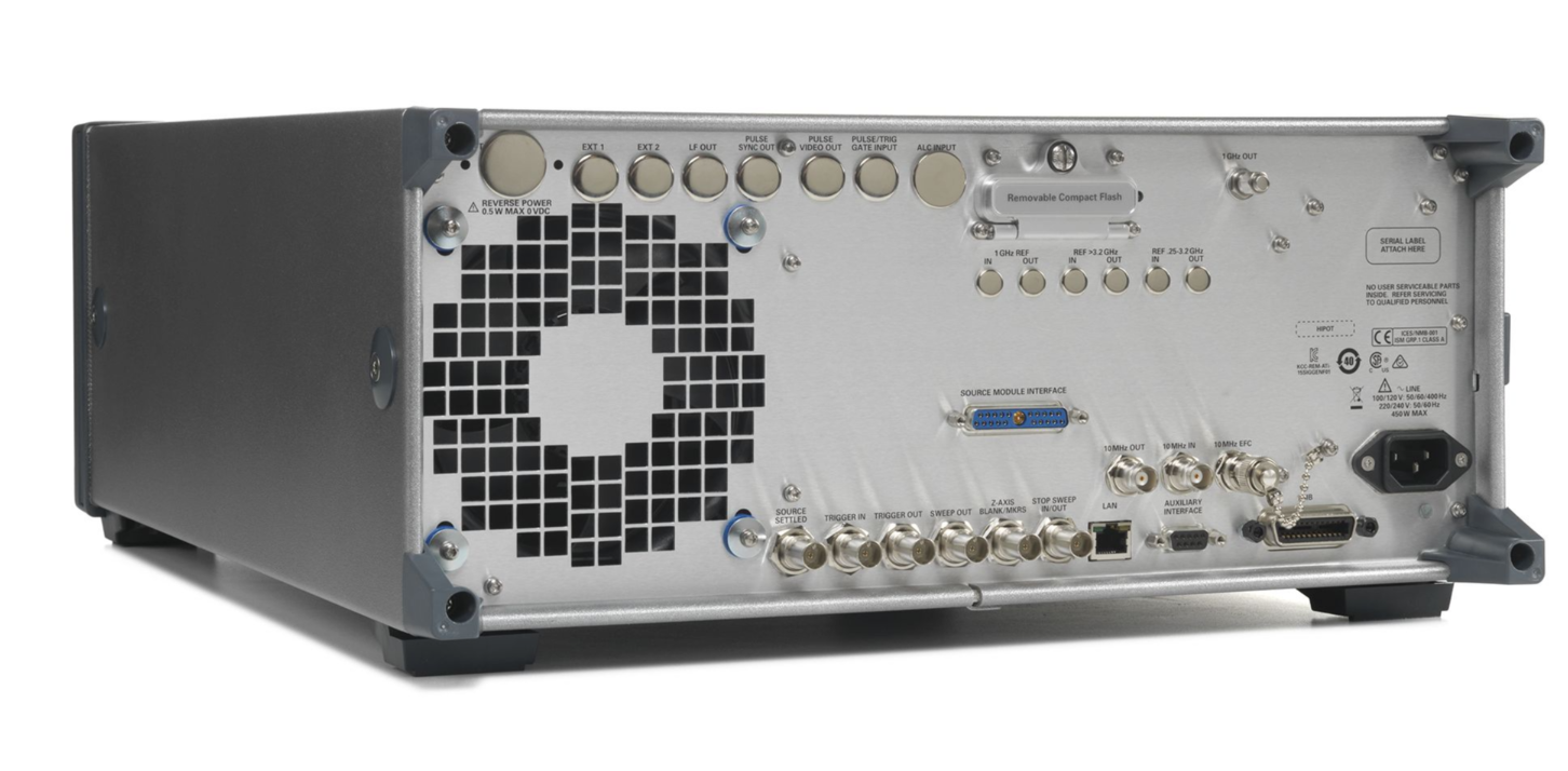
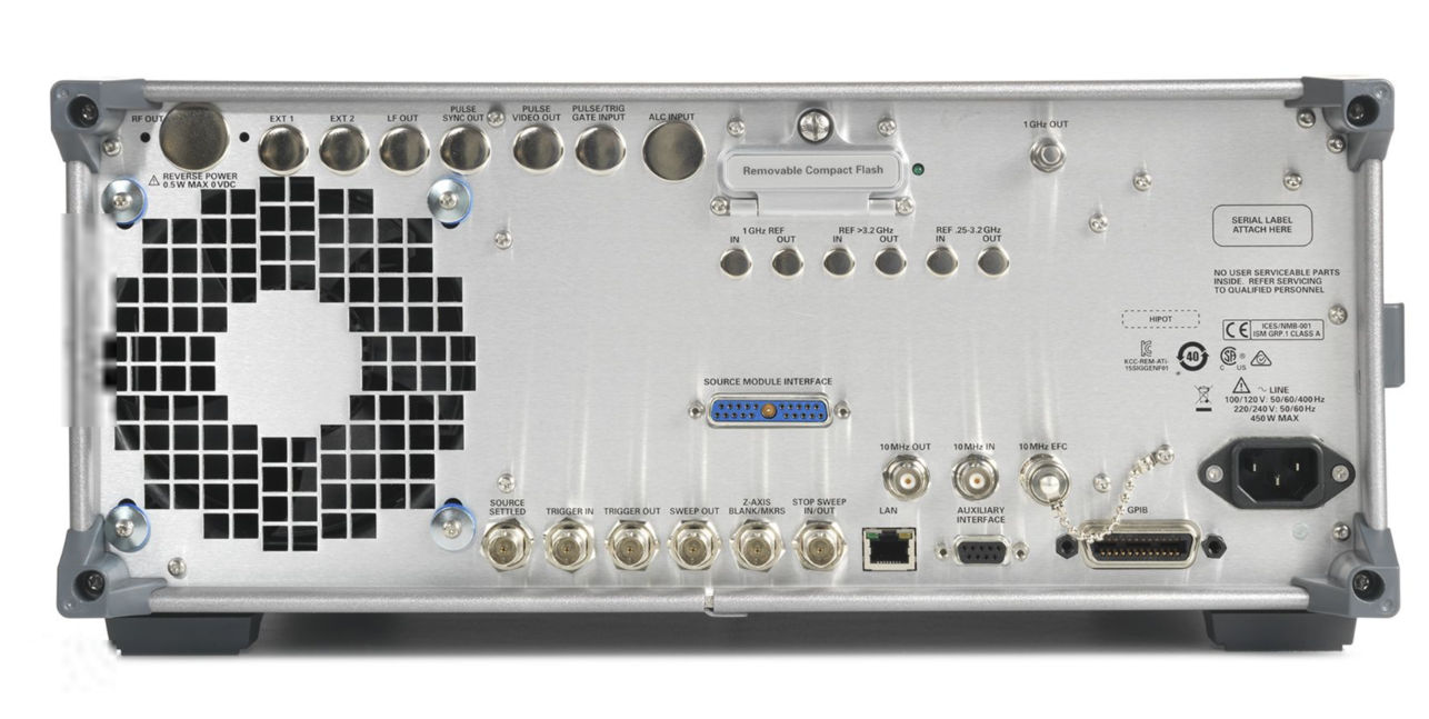
条件:Front panel connectors (all connectors are BNC female unless otherwise noted.) 98
Options 513, 520 and 521 Precision APC-3.5 male, or Type-N female with Option 1ED Caution: Option 521 output power > 1 Watt
ALC input Used for negative external detector leveling. Nominal input impedance 120 kΩ,damage level ±15 V.
LF output Outputs the internally generated LF source. Nominal output impedance 50 Ω.
External input 1 Drives either AM,FM,or φM. Nominal input impedance 50 or 600 Ω,damage levels are 5 Vrms and 10 Vpeak.
External input 2 Drives either AM, FM, or φM. Nominal input impedance 50 or 600 Ω, damage levels are 5 Vrms and 10 Vpeak.
pulse modulation. Nominal impedance 50 Ω. Damage levels are 5 V rms and 10 Vpeak.
Pulse video out Outputs a signal that follows the RF output in all pulse modes. TTL-level compatible, nominal source impedance 50 Ω.
Pulse sync out Outputs a synchronizing pulse,nominally 50 ns width,during internal and triggered pulse modulation.
TTL-level compatible, nominal source impedance 50 Ω.
RF output Output impedance
50 Ω (nom)
Options 532, 540, and 550 Precision 2.4 mm male; plus
2.4 –2.4 mm and 2.4 –2.9 mm female adapters
Option 567 Precision 1.85 mm male;plus
1.85 – 1.85 mm and 2.4 – 2.9 mm female adapters
Pulse/trigger gate input Accepts input signal for external fast pulse modulation. Also accepts external trigger pulse input for internal
98 Digital inputs and outputs are 3.3 V CMOS unless indicated otherwise. Inputs will accept 5 V CMOS
3 V CMOS,or TTL voltage
条件:Used for RS-232 serial communication and for primary/secondary source synchronization.
(9-pin subminiature female connector). For primary/secondary operation,use Keysight part number
8120-8806
GPIB Allows communication with compatible devices
条件:10 MHz output Outputs internal or external reference signal. Nominal output impedance 50 Ω. Nominal output power
LAN Allows
10BaseT LAN communication
10 MHz input
Accepts a
10 MHz external reference (timebase) input.
Nominal input impedance
50 Ω
Damage levels >
+10 dBm
+8 dBm.
Supplies a voltage proportional to the RF power or frequency sweep ranging from 0 volts at the start of sweep to +10 volts
(nom) at the end of sweep, regardless of sweep width
During CW operation, supplies a voltage proportional to the output frequency
+10 volts (nom)
corresponding to the maximum specified frequency
When connected to a Keysight 8757D scalar network analyzer (Option
007), generates a selectable number of equally
spaced
1 μs pulses (nom) across a ramp (analog) sweep. Number of pulses can be set from 101 to 1601 by remote control
Output impedance: < 1 Ω (nom), can drive
2 kΩ.
Open-collector,TTL-compatible input/output. In ramp sweep operation,provides low level (nominally
0 V) during sweep
retrace and bandcross intervals, and high level during the forward portion of the sweep. Sweep will stop when grounded
条件:Trigger input Accepts 3.3 V CMOS signal for triggering point-to-point in manual sweep mode,or to trigger start of LF sweep.
Source module interface Keysight 83550 Series mm source modules: Provides bias, flatness correction and leveling connections.
Outputs a TTL signal. High at start of dwell,or when waiting for point trigger;low when dwell is over or point trigger is
received. In ramp sweep mode, provides 1601 equally-spaced
1 μs pulses (nom) across a ramp sweep. When using LF
Out,provides
2 μs pulse at start of LF sweep .
Damage levels ≥ +10 V or ≤
–4 V.
OML SxxMS-AG mm source modules:Provides power to the module and returns frequency multiplication information from
Source settled Provides an output trigger that indicates when the signal generator has settled to a new frequency or power level. High
以上指标摘自厂家官方数据手册,完整定义、测试条件与保证值口径以手册为准。完整指标、测试条件与定义口径请见产品页「软件和手册 |白皮书」栏目中的官方数据手册。
是德科技 | KEYSIGHT · onetest 仪器资源库


 客服









 粤公网安备44030902003758