是德科技 | KEYSIGHT
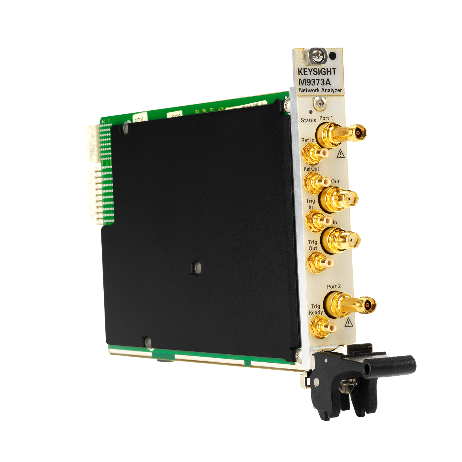
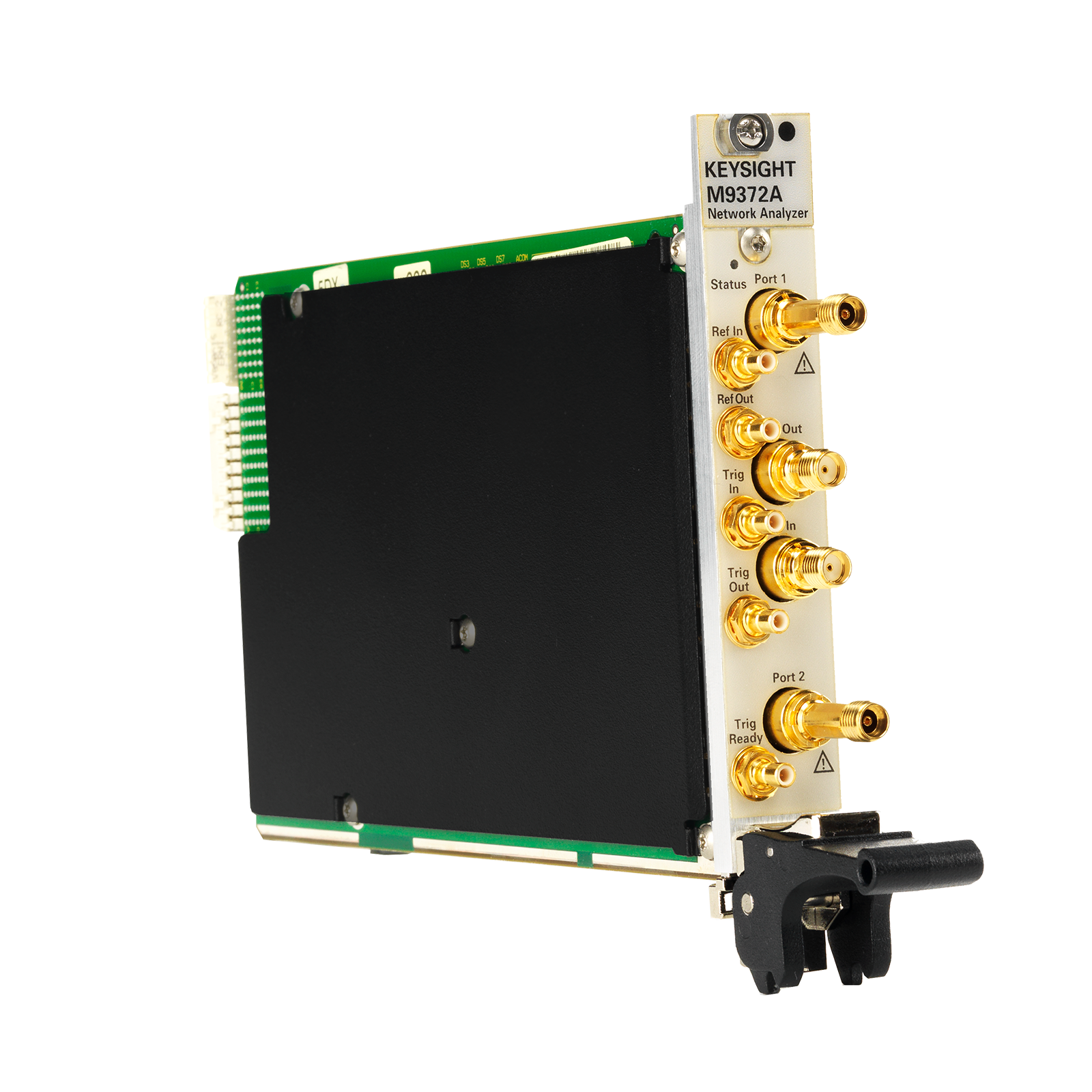
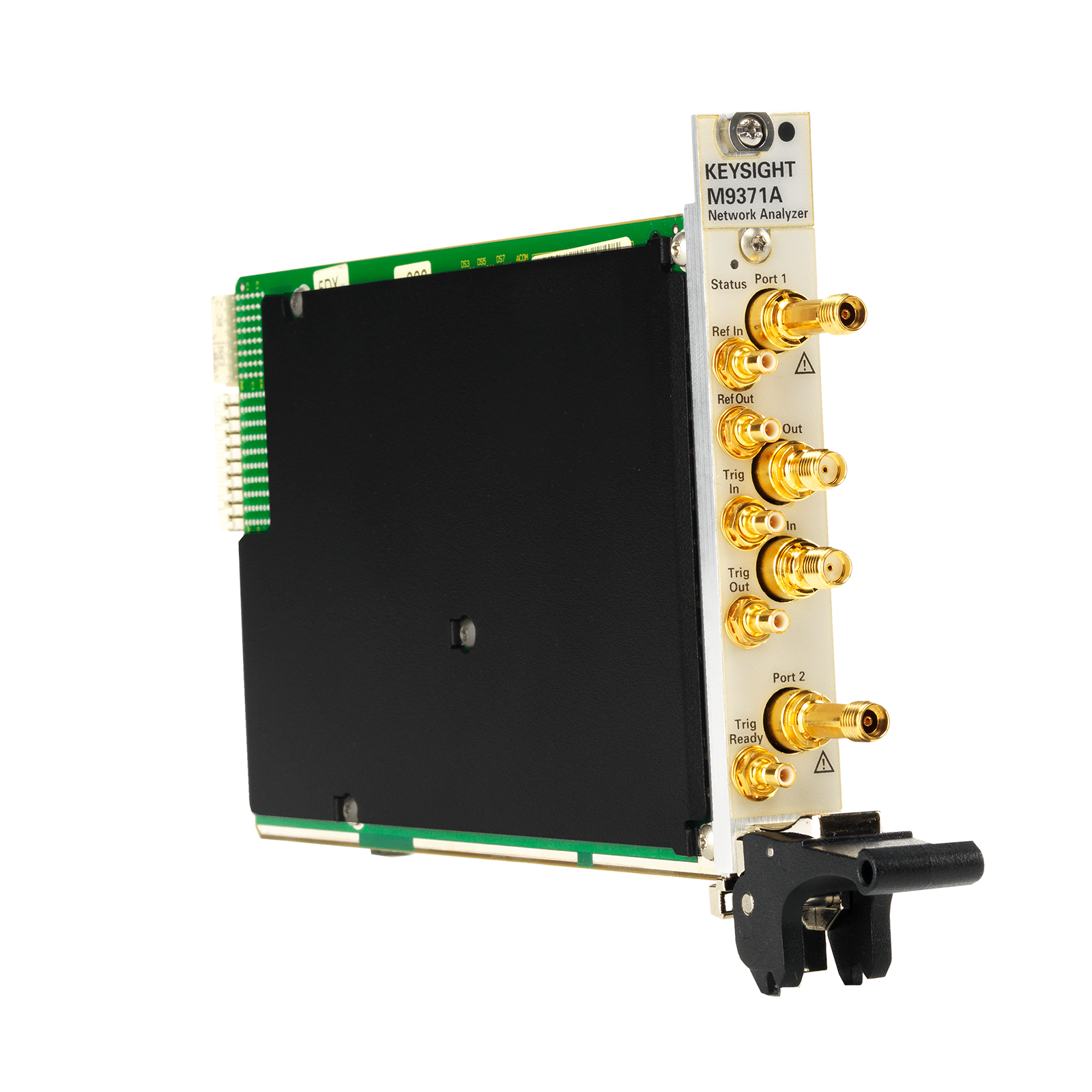
M9371A 300kHz至6.5GHz 矢量网络分析仪 115dB 详细指标
Modular PXI Vector Network Analyzers
M9375A
300 kHz to 26.5 GHz
When you need to measure basic S-parameters, the right mix of speed, performance and footprint gives you an edge. Sharpen your edge with the
Get more VNA in less space
条件:characterize many devices -- two-port or multiport -- using a single PXI chassis.
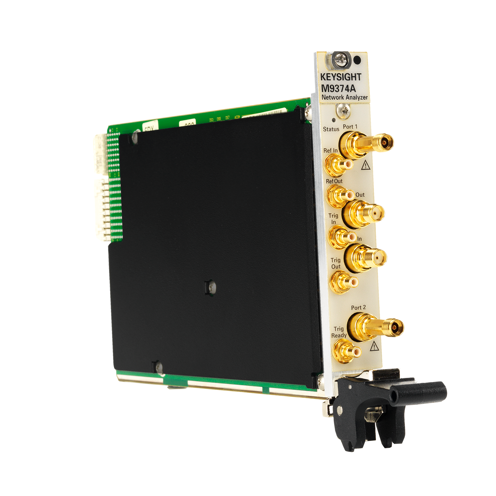
The Keysight PXI VNA is a full two-port VNA that fits in just one slot. The PXI VNA also performs fast, accurate measurements and reduces your cost-of-test by letting you simultaneously
It offers the best PXI VNA performance on key specifications such as dynamic range, measurement speed, and trace noise. Each module is a completely independent two-port
network analyzer and up to 16 modules can be
added to a chassis for multi-site and multiport applications. All ports are fully synchronous so multiple ports can be measured simultaneously with multiport error correction applied. For more
Achieve confidence and continuity in measurements
The M937xA extends Keysight’s expertise in
metrology to the modular form factor. It provides the same quality results you have come to expect in our vector network analyzers. Here are a few examples of ways that we continue to provide
measurement quality and continuity
• Dynamic range: >
114 dB at 9 GHz
> 110 dB at 20 GHz
• Trace noise: <
0.003 dB
• Sweep speed: 18 to 33 msec across
401
• Maximum leveled power: up to +7 dBm
• Stability
0.005 dB/°C up to 4 GHz
<0.02 dB/°C up to 26.5 GHz
• Electronic calibration (ECal): enables fast, easy and accurate calibrations
Maintain hardware compliance
条件:package. It is an ideal deployment platform for many automated test systems.
Pay for only the frequency range you need with the widest choice of frequency ranges from 300 kHz up to 26.5 GHz.
The M937xA is PXI compliant and designed to
benefit from fast data interfaces. The PXI VNA can be integrated with other test and automation modules in either a PXIe or Hybrid slot. The PXI format offers high performance in a small, rugged
条件:PNA. Users can quickly configure the instrument parameters and perform calibrations.
Keysight soft front panels provide easy to use instrument communications. The graphical user interface guides developers through module setup using a similar look and feel as the popular
条件:system, whether they are PXI, PXIe, or AXIe. From here you can view information about the installed software or launch the modules’ soft front panel directly from Keysight Connection Expert (KCE).
Keysight IO Libraries Suite offers fast and easy connection to both traditional and modular instruments. The Keysight IO Libraries Suite helps you by displaying all of the modules in your
KCE offers an easy way to find the correct driver for your instrument.
The M937xA PXI VNA is supplied with a
comprehensive portfolio of module drivers, documentation, examples, and software tools to help you quickly develop test systems with your software platform of choice. The module comes
with IVI-COM, IVI-C, LabVIEW and MATLAB software drivers that work in the most popular
Easy software integration
To help you get started and complete complex tasks quickly, the module software support provides context sensitive help, complete documentation and code examples that allow
quick module set up. These code examples can be easily modified, so that the PXI VNA can be quickly integrated into a test system. Included are application code examples for LabVIEW,
The graphical user interface guides test engineers using a similar look and feel as Keysight’s popular
条件:Table 7. Nominal power (preset power level) .............................................. 13
Definitions .........................................................................................................
6
System Specifications ................................ ................................ ...................
7
Table 1. Frequency Information ......................................................................
7
Table 2. Noise floor and dynamic range .........................................................
8
Corrected performance ................................ ................................ ................
9
Table 3. With N4691B electronic calibration module ...................................
9
Table 4. With 85052D standard mechanical 3.5 mm calibration kit ........
11
Uncorrected System Performance ................................ .............................
12
Table 5. Uncorrected error terms - specification ........................................
12
Test Port Output ................................ ................................ .........................
13
Table 6. Maximum output port power ..........................................................
13
Table 8. Power Range ....................................................................................
13
Table 9. Power level accuracy .......................................................................
14
Table 10. Source harmonics ..........................................................................
14
Table 11. Non-harmonic spurs .....................................................................
15
Table 12. Phase noise ....................................................................................
15
Test Port Input ................................ ................................ ............................
16
Table 13. Test port input damage level ........................................................
16
Table 14. Receiver compression level for 0.1 dB compression (typical) ...
16
Table 15. Receiver compression versus test port power level (specified)
16
Table 16. Receiver Level Accuracy ...............................................................
17
Table 18. Magnitude trace noise (1 kHz IF bandwidth, -5 dBm power) ....
19
Table 19. Magnitude trace noise (characteristic performance
+6 dBm
power) .............................................................................................................
19
Table 20. Magnitude trace noise (typical performance, +6 dBm power) ..
19
Table 21. Phase trace noise (1 kHz IF bandwidth, -5 dBm power) ............
19
Table 22. Phase trace noise (characteristic performance
+6 dBm power)20
Table 23. Phase trace noise (typical performance, +6 dBm power) ..........
20
Table 24. Temperature stability (typical) ......................................................
20
Dynamic Accuracy................................ ................................ .......................
21
Table 25. Dynamic Accuracy 4 GHz to 26.5 GHz ........................................
21
General Information ................................ ................................ ....................
23
Table 26. System requirements ....................................................................
23
Table 27. Environmental and Physical Specifications .................................
24
Table 28. Regulatory and Safety Compliance ..............................................
25
Table 29. Physical Size and Weight ..............................................................
26
Table 30. Electrical Power .............................................................................
26
Table 31. Front Panel Information ................................................................
26
Table 32. Measurement speed (milliseconds) .............................................
28
Table 33. Measurement capabilities .............................................................
30
Table 34. Software .........................................................................................
35
条件:distribution, measurement uncertainties, and changes in performance due to environmental conditions. All
46°C (unless otherwise stated). The following conditions must be met:
▪ Instrument has been turned on for 60 minutes with PXI VNA application running.
Warranted performance. Specifications include guardbands to account for the expected statistical performance
specifications and characteristics apply over a 25°C ±5°C range ambient and module temperature between
33°C to
▪ Instrument is within its calibration cycle
▪ Instrument remains at a stable surrounding environment temperature (between
-10°C to 55°C) for 60 minutes
条件:the field and is not covered by the product warranty. A characteristic includes the same guardbands as a specification.
A performance parameter that the product is expected to meet before it leave s the factory, but that is not verified in
Expected performance of an average unit at a stable temperature between 25°C
±5°C for 60 minutes prior to turn-on
and during operation; does not include guardbands. It is not covered by the product warranty. The instrument must be
条件:how well "known" they are, plus system repeatability, stability, and noise.
Indicates performance after error correction (calibration). It is determined by the quality of calibration standards and
Indicates instrument performance without error correction. The uncorrected performance affects the stability of a
条件:Temperatures referred to in this document are defined as follows:
▪ Full temperature range = individual module temperature of 10°C to 70°C, as reported by the module, and
environment temperature of 0°C to 55°C.
▪ Controlled temperature range = individual module temperature of 33°C to 46°C, as reported by the module, and
environment temperature of 20°C to 30°C.
条件:the two specifications at that frequency, unless otherwise indicated.
For all tables in this document, the specified performance at the exact frequency of a break is the degraded value of
Table
1. Frequency Information
M9375A
300 kHz to 26.5 GHz
条件:System impedance 50 Ω (nominal) 75 Ω with appropriate adapter and calibration kit
Aging rate <
3.5 ppm/year
Temperature stability ±1 ppm over
0 to 55 ºC
Table
2. Noise floor and dynamic range
Frequency range Noise Floor1 (dBm)
Dynamic Range2
Dynamic Range3
条件:the dynamic range. Crosstalk only limits the dynamic range for IF bandwidths < 1 kHz.
Range4 (dB)
(characteristic) 300 kHz to < 10 MHz -- -- 111 97 10 to < 250 MHz -98 98 110 95 250 MHz to 1 GHz -108 115 122
114
> 1 to 4 GHz -108 115 122
115
> 4 to 6.5 GHz -108 115 122
115
> 6.5 to 9 GHz -108 114 121
114
> 9 to 14 GHz -108 114 120
110
> 14 to 18 GHz -108 112 119
100
> 18 to 20 GHz -108 110 118
98
> 20 to 24 GHz -98 95 104
82
> 24 to 26.5 GHz -- -- 95
65
1 Noise floor in a
10 Hz IF bandwidth
2 System dynamic range = source maximum output power minus receiver noise floor at 10 Hz IF
bandwidth. Does not include single module crosstalk effects. 3 System dynamic range = source maximum output power minus receiver noise floor at 10 Hz IF bandwidth. Does not include single module crosstalk effects. 4 Effective dynamic range is when the crosstalk is greater than the noise floor, and thus crosstalk limits
Custom Uncertainty Calculator
条件:either the N4691B Electronic Calibration Module, or the 85052D Standard Mechanical Calibration Kit.
This document provides technical specifications for the corrected performance of the PXI VNA using
To determine transmission and reflection uncertainty curves with other calibration kits, p lease download
Table
3. With N4691B electronic calibration module5
Corrected error terms (dB) - 300 kHz to 24 GHz
条件:5 Measured with 10 Hz IF bandwidth, no averaging applied to data, environmental temperature = 23 °C
(±3 °C) with < 1 °C deviation from calibration temperature, isolation calibration performed.
Mag Phase ° Mag Phase ° 300 kHz to < 2 MHz 31 29 29 ±0.21 ±1.4 ±0.12 ±0.74 2 MHz to 1 GHz 41 36 41 ±0.021 ±0.14 ±0.061
±0.40
> 1 to 2 GHz 52 47 52 ±0.0066 ±0.044 ±0.020
±0.14
> 2 to 4.5 GHz 48 45 48 ±0.015 ±0.095 ±0.031
±0.20
> 4.5 to 6.5 GHz 48 45 48 ±0.020 ±0.14 ±0.031
±0.20
> 6.5 to 9 GHz 48 45 45 ±0.033 ±0.22 ±0.031
±0.20
> 9 to 14 GHz 46 42 43 ±0.053 ±0.35 ±0.041
±0.27
> 14 to 20 GHz 46 42 42 ±0.067 ±0.44 ±0.041
±0.27
> 20 to 24 GHz 44 40 40 ±0.11 ±0.69 ±0.051
±0.34
Reflection 不确定度 (magnitude 和相位)
Table 4. With 85052D standard mechanical 3.5 mm calibration kit
6
Corrected error terms (dB) – 300 kHz to 24 GHz
条件:Transmission uncertainty (magnitude and phase) 6 Measured with 10 Hz IF bandwidth, no averaging applied to data, environmental temperature = 23 °C (±3 °C) with < 1 °C deviation from calibration temperature, isolation calibration performed.
Mag Phase ° Mag Phase ° 300 kHz to < 2 MHz 42 36 41 ±0.069 ±0.46 ±0.0030 ±0.020 2 MHz to 1 GHz 42 36 42 ±0.019 ±0.13 ±0.0030
±0.020
> 1 to 2 GHz 42 36 42 ±0.021 ±0.14 ±0.0030
±0.020
> 2 to 4 GHz 38 30 38 ±0.055 ±0.37 ±0.0041
±0.027
> 4 to 6.5 GHz 38 30 38 ±0.089 ±0.59 ±0.0041
±0.027
> 6.5 to 9 GHz 36 28 35 ±0.16 ±1.1 ±0.0080
±0.053
> 9 to 14 GHz 36 28 35 ±0.2 ±1.4 ±0.0080
±0.053
> 14 to 20 GHz 36 28 35 ±0.24 ±1.6 ±0.0080
±0.053
> 20 to 24 GHz 30 25 29 ±0.45 ±3.0 ±0.011
±0.073
条件:Specifications apply to following conditions:
• Over environmental temperature of 25 °C
±5 °C
• Cable loss not included in transmission tracking
条件:• Cross-talk measurement conditions: normalized to a thru, measured with shorts on all ports, 10
Hz IF bandwidth, averaging factor of 8, alternate mode, source power set to the specified
Cross-talk (typical) 300 kHz to < 2 MHz 7 9 9 ± 2 ± 2 97 2 MHz to 1 GHz 20 19 21 ± 2 ± 2
95
> 1 to 2 GHz 20 20 19 ± 2 ± 2
123
> 2 to 4 GHz 18 20 13 ± 2 ± 2
121
> 4 to 6.5 GHz 15 15 11 ± 2 ± 2
121
> 6.5 to 9 GHz 10 11 8 ± 2 ± 2
119
> 9 to 14 GHz 9 9 7 ± 2 ± 2
110
> 14 to 20 GHz 4 6 6 ± 2 ± 2
98
> 20 to 24 GHz 3 5 4 ± 2.5 ± 2.5
82
Table
6. Maximum output port power
条件:Table 7. Nominal power (preset power level)
| Frequency | Range | Specification | Typical |
|---|
| 300 kHz to < 10 MHz -- | +3 dBm | | |
| 10 to < | 250 MHz | 0 dBm | +3 dBm |
| 250 MHz to 6.5 GHz +7 dBm | +10 dBm | | |
| > 6.5 to 9 GHz +6 dBm | +9 dBm | | |
| > 9 to 14 GHz +6 dBm | +8 dBm | | |
| > 14 to 18 GHz +4 dBm | +7 dBm | | |
| > 18 to 20 GHz +2 dBm | +6 dBm | | |
| > 20 to 24 GHz -3 dBm | +1 dBm | | |
| > 24 to 26.5 GHz -- | -5 dBm | | |
300 kHz to < 10 MHz --
250 MHz to 6.5 GHz +7 dBm
| Frequency | Range | Specification | Typical |
|---|
| 300 kHz to < | 10 MHz -- | +3 dBm to | -40 dBm |
| 10 to < | 250 MHz | 0 dBm to | -40 dBm |
| 250 MHz to 6.5 GHz | +7 to -40 dBm | | |
| > 6.5 to 9 GHz | +6 to -40 dBm | | |
| > 9 to 14 GHz | +6 to -40 dBm | | |
| > 14 to 18 GHz | +4 to -40 dBm | | |
| > 18 to 20 GHz | +2 to -40 dBm | | |
| > 20 to 24 GHz | -3 to -40 dBm | | |
| > 24 to 26.5 GHz -- | -5 to -40 dBm | | |
| Table | 9. Power level accuracy | | |
Table
Range
9. Power level accuracy
Frequency range -40 dBm ≤ P < dBm
-30
-30 dBm ≤ P < max
-30 dBm ≤ P < max
port spec power 300 kHz to < 2 MHz -- -- ±1.3 ±1.0 2 to < 10 MHz -- -- ±2.5 ±2.2 10 to < 250 MHz ±4.5 ±2.5 ±1.0
±0.7
250 MHz to 1 GHz ±1.5 ±1.5 ±0.4
±0.4
> 1 to 6.5 GHz ±1.5 ±1.5 ±0.3
±0.3
> 6.5 to 20 GHz ±1.5 ±1.5 ±0.5
±0.5
> 20 to 24 GHz ±3.0 ±3.0 ±0.8
±0.8
> 24 to 26.5 GHz -- -- ±1.8
±1.8
Programmable power resolution
0.01 dB typical
Table
10. Source harmonics7
| Frequency | Range | Specification | Typical |
|---|
| 300 kHz to < 100 MHz -- | -6 dBc | | |
| 100 MHz to 2 GHz -- | -6 dBc | | |
| 2 to 4 GHz -- | -10 dBc | | |
| > 4 to 6.5 GHz -- | -11 dBc | | |
| > 6.5 to 14 GHz -- | -14 dBc | | |
| > 14 to 20 GHz -- | -8 dBc | | |
| > 20 to 26.5 GHz -- | -5 dBc | | |
| 7 At maximum specified power, includes sub-harmonics. | | | |
| Table | 11. Non-harmonic spurs8 | | |
300 kHz to < 100 MHz --
7 At maximum specified power, includes sub-harmonics.
Table
Range
11. Non-harmonic spurs8
| Frequency | Range | Specification | Typical |
|---|
| 300 kHz to < 10 MHz -- | -44 dBc | | |
| 10 MHz to 10 GHz -- | -36 dBc | | |
| > 10 to 20 GHz -- | -30 dBc | | |
| > 20 to 26.5 GHz -- | -24 dBc | | |
| Table | 12. Phase noise9 | | |
300 kHz to < 10 MHz --
条件:8 At nominal (preset) power of -5 dBm.
| Frequency | Range | Specification | Typical |
|---|
| 300 kHz to < 2 MHz -- | -100 dBc/Hz | | |
| 2 MHz to 2.5 GHz -- | -90 dBc/Hz | | |
| > 2.5 to 5 GHz -- | -84 dBc/Hz | | |
| > 5 to 10 GHz -- | -78 dBc/Hz | | |
| > 10 to 20 GHz -- | -72 dBc/Hz | | |
| > 20 to 26.5 GHz -- | -66 dBc/Hz | | |
| 9 Phase noise in dBc/Hz, for output ports | 1 or | 2; typical values for | 1 kHz, 10 kHz, and 100 kHz offsets. |
9 Phase noise in dBc/Hz, for output ports
Specification
2; typical values for
Typical
1 kHz, 10 kHz, and 100 kHz offsets.
Table
13. Test port input damage level
300 kHz to 26.5 GHz > +20 dBm, > ±35 VDC, >
1000V ESD
Table
14. Receiver compression level for 0.1 dB compression (typical)
| Frequency | Range | Specification | Typical |
|---|
| 300 kHz to < 10 MHz -- > | +7 dBm | | |
| 10 to < 250 MHz -- > | +8 dBm | | |
| 250 MHz to 1 GHz -- > | +12 dBm | | |
| > 1 to 4 GHz -- > | +10 dBm | | |
| > 4 to 6.5 GHz -- > | +8 dBm | | |
| > 6.5 to 9 GHz -- > | +8 dBm | | |
| > 9 to 14 GHz -- > | +6 dBm | | |
| > 14 to 18 GHz -- > | +5 dBm | | |
| > 18 to 20 GHz -- > | +10 dBm | | |
| > 20 to 24 GHz -- > | +8 dBm | | |
| > 24 to 26.5 GHz -- > | +4 dBm | | |
| Table | 15. Receiver compression versus test port power level (specified) | | |
300 kHz to < 10 MHz -- >
10 to < 250 MHz -- >
> 4 to 6.5 GHz -- >
> 6.5 to 9 GHz -- >
> 14 to 18 GHz -- >
> 18 to 20 GHz -- >
> 20 to 24 GHz -- >
> 24 to 26.5 GHz -- >
Table
Range
15. Receiver compression versus test port power level (specified)
Magnitude (dB) Phase (degrees) 10 MHz to 250 MHz 0 .15
1.1
> 250 MHz to 1 GHz
7 .12 .9
> 4 to 6.5 GHz
7 .12 .9
> 6.5 to 9 GHz 6 .12
1.0
> 9 to 14 GHz 6 .16
1.3
>14 to 18 GHz 4 .16
1.5
>18 to 20 GHz 2 .13
1.6
>20 to 24 GHz -3 .11
1.0
Table
16. Receiver Level Accuracy
Frequency Range Accuracy at -5 dBm input power level
300 kHz to 10 MHz --
10 MHz to 26.5 GHz
±0.5 dB1
1 Factory or service calibration required. Calibration can be refreshed any time using service routine.
Accuracy across N-ports can be achieved with a multi-port cal.
Table
17. Noise floor (10 Hz IF bandwidth)
| Frequency | Range | Specification | Typical |
|---|
| 300 kHz to < 10 MHz -- | -108 dBm | | |
| 10 to < | 250 MHz | -98 dBm | -107 dBm |
| 250 MHz to 1 GHz -108 dBm | -112 dBm | | |
| > 1 to 4 GHz -108 dBm | -112 dBm | | |
| > 4 to 6.5 GHz -108 dBm | -112 dBm | | |
| > 6.5 to 9 GHz -108 dBm | -112 dBm | | |
| > 9 to 14 GHz -108 dBm | -112 dBm | | |
| > 14 to 20 GHz -108 dBm | -112 dBm | | |
| > 20 to 24 GHz -98 dBm | -103 dBm | | |
| > 24 to 26.5 GHz -- | -100 dBm | | |
300 kHz to < 10 MHz --
250 MHz to 1 GHz -108 dBm
> 4 to 6.5 GHz -108 dBm
> 6.5 to 9 GHz -108 dBm
> 9 to 14 GHz -108 dBm
> 14 to 20 GHz -108 dBm
> 20 to 24 GHz -98 dBm
噪声底规格 lines 和典型值 measured 值
Table 18. Magnitude trace noise (1 kHz IF bandwidth
-5 dBm power)
噪声底规格 lines 和典型值 measured 值
| Frequency | Range | Specification | Typical |
|---|
| 300 kHz to < 10 MHz -- | 0.0020 dB rms | | |
| 10 MHz to 4 GHz 0.003 dB rms | 0.0010 dB rms | | |
| > 4 to 6.5 GHz 0.003 dB rms | 0.0010 dB rms | | |
| > 6.5 to 9 GHz 0.003 dB rms | 0.0010 dB rms | | |
| > 9 to 14 GHz 0.003 dB rms | 0.0010 dB rms | | |
| > 14 to 20 GHz 0.003 dB rms | 0.0010 dB rms | | |
| > 20 to 24 GHz 0.006 dB rms | 0.0015 dB rms | | |
| > 24 to 26.5 GHz -- | 0.0020 dB rms | | |
| Table 19. Magnitude trace noise (characteristic performance | +6 dBm power) | | |
| Frequency Range | 10 kHz IF bandwidth | 100 kHz IF bandwidth | 600 kHz IF bandwidth |
| 250 MHz to 10 GHz | 0.0020 dB rms | 0.0055 dB rms | 0.0120 dB rms |
| > 10 to 14 GHz | 0.0030 dB rms | 0.0075 dB rms | 0.0160 dB rms |
| Table 20. Magnitude trace noise (typical performance | +6 dBm power) | | |
| Frequency Range | 10 kHz IF bandwidth | 100 kHz IF bandwidth | 600 kHz IF bandwidth |
| 250 MHz to 10 GHz | 0.001 dB rms | 0.003 dB rms | 0.007 dB rms |
| > 10 to 14 GHz | 0.002 dB rms | 0.004 dB rms | 0.008 dB rms |
| Table 21. Phase trace noise (1 kHz IF bandwidth | -5 dBm power) | | |
300 kHz to < 10 MHz --
10 MHz to 4 GHz 0.003 dB rms
> 4 to 6.5 GHz 0.003 dB rms
> 6.5 to 9 GHz 0.003 dB rms
> 9 to 14 GHz 0.003 dB rms
> 14 to 20 GHz 0.003 dB rms
> 20 to 24 GHz 0.006 dB rms
Table 19. Magnitude trace noise (characteristic performance
Frequency Range
Specification
100 kHz IF bandwidth
Typical
600 kHz IF bandwidth
250 MHz to 10 GHz
Specification
0.0055 dB rms
> 10 to 14 GHz
Specification
0.0075 dB rms
Table 20. Magnitude trace noise (typical performance
Frequency Range
Specification
100 kHz IF bandwidth
Typical
600 kHz IF bandwidth
250 MHz to 10 GHz
Specification
0.003 dB rms
> 10 to 14 GHz
Specification
0.004 dB rms
Table 21. Phase trace noise (1 kHz IF bandwidth
噪声底规格 lines 和典型值 measured 值
| Description | Specification | Typical | value |
|---|
| 300 kHz to < 10 MHz -- | 0.020 deg | | |
| 10 MHz to 4 GHz 0.030 deg | 0.010 deg | | |
| > 4 to 6.5 GHz 0.030 deg | 0.010 deg | | |
| > 6.5 to 9 GHz 0.030 deg | 0.010 deg | | |
| > 9 to 14 GHz 0.030 deg | 0.010 deg | | |
| > 14 to 20 GHz 0.030 deg | 0.010 deg | | |
| > 20 to 24 GHz 0.060 deg | 0.015 deg | | |
| > 24 to 26.5 GHz -- | 0.020 deg | | |
| Table 22. Phase trace noise (characteristic performance | +6 dBm power) | | |
| Frequency Range | 10 kHz IF bandwidth | 100 kHz IF bandwidth | 600 kHz IF bandwidth |
| 250 MHz to 8.5 GHz | 0.010 deg. | 0.025 deg. | 0.060 deg. |
| > 8.5 to 14 GHz | 0.020 deg. | 0.055 deg. | 0.120 deg. |
| Table 23. Phase trace noise (typical performance | +6 dBm power) | | |
| Frequency Range | 10 kHz IF bandwidth | 100 kHz IF bandwidth | 600 kHz IF bandwidth |
| 250 MHz to 8.5 GHz | 0.006 deg. | 0.014 deg. | 0.033 deg. |
| > 8.5 to 14 GHz | 0.010 deg. | 0.030 deg. | 0.060 deg. |
| Table | 24. Temperature stability (typical) | | |
| Frequency range Magnitude stability Phase stability 300 kHz to < 10 MHz ±0.005 dB/°C ±0.20 Degree/°C | 10 MHz to | 4 GHz | ±0.005 dB/°C ±0.10 Degree/°C |
| > 4 to 6.5 GHz ±0.010dB/°C | ±0.15 Degree/°C | | |
| > 6.5 to 9 GHz ±0.015 dB/°C | ±0.20 Degree/°C | | |
| > 9 to 14 GHz ±0.015 dB/°C | ±0.40 Degree/°C | | |
| > 14 to 20 GHz ±0.020 dB/°C | ±0.50 Degree/°C | | |
| > 20 to 26.5 GHz ±0.020 dB/°C | ±0.60 Degree/°C | | |
300 kHz to < 10 MHz --
10 MHz to 4 GHz 0.030 deg
> 4 to 6.5 GHz 0.030 deg
> 6.5 to 9 GHz 0.030 deg
> 9 to 14 GHz 0.030 deg
> 14 to 20 GHz 0.030 deg
> 20 to 24 GHz 0.060 deg
Table 22. Phase trace noise (characteristic performance
Specification
+6 dBm power)
Frequency Range
Specification
10 kHz IF bandwidth
Typical
100 kHz IF bandwidth
value
600 kHz IF bandwidth
Table 23. Phase trace noise (typical performance
Specification
+6 dBm power)
Frequency Range
Specification
10 kHz IF bandwidth
Typical
100 kHz IF bandwidth
value
600 kHz IF bandwidth
Table
Specification
24. Temperature stability (typical)
Frequency range Magnitude stability Phase stability 300 kHz to < 10 MHz ±0.005 dB/°C ±0.20 Degree/°C
value
±0.005 dB/°C ±0.10 Degree/°C
> 4 to 6.5 GHz ±0.010dB/°C
Specification
±0.15 Degree/°C
> 6.5 to 9 GHz ±0.015 dB/°C
Specification
±0.20 Degree/°C
> 9 to 14 GHz ±0.015 dB/°C
Specification
±0.40 Degree/°C
> 14 to 20 GHz ±0.020 dB/°C
Specification
±0.50 Degree/°C
> 20 to 26.5 GHz ±0.020 dB/°C
Specification
±0.60 Degree/°C
条件:Accuracy of the test port input power relative to the reference input power level.
Table 25. Dynamic Accuracy
4 GHz to 26.5 GHz
Although labeled ‘M9375A’, these graphs apply to all models.
Dynamic accuracy
4 GHz (magnitude and phase)
Dynamic accuracy
6.5 GHz (magnitude and phase)
Dynamic accuracy
9 GHz (magnitude and phase)
Dynamic accuracy
14 GHz (magnitude and phase)
Dynamic accuracy
20 GHz (magnitude and phase)
Dynamic accuracy
26.5 GHz (magnitude and phase)
Table
26. System requirements
Operating systems Windows
10 (64 bit)
Processor speed Intel Core i7
10th Generation or later recommended
Available memory 4 GB minimum
16 GB recommended
Available disk space
4 GB minimum
Display resolution 1024 X
768 minimum
USB USB
3.0 port directly connected to Intel chipset
Keysight IO libraries Keysifht IO Libraries Suite: 2022 update
1 (18.2.28014.7) or later
Instrument drivers · Table 27. 环境和物理规格
条件:limited to, temperature, humidity, shock, vibration, altitude, and power line conditions.
Description Samples of this product have been type tested in accordance with the Keysight
Environmental Test Manual and verified to be robust against the environmental
stresses of Storage, Transportation and End-use; those stresses include, but are not
Test Methods are aligned with IEC
60068-2 and levels are similar to MIL-PRF-28800F
Non-operating 0 to 55 °C ambient
10 to 70 °C module temperature
-40 to +70 °C
Humidity Type tested at 95%
+40 °C
Altitude – Operating Up to 15,000 feet (4,572 meters)
Altitude – Non-operating Up to 15,000 feet (4,572 meters)
Intrusion protection IP 30 IEC/EN
60529
Trig In and Trig. Out, Trig. Ready
3.5 mm female
Table
28. Regulatory and Safety Compliance
Complies with the essential requirements of the European EMC Directive as well as
current editions of the following standards (dates and editions are cited in the
Declaration of Conformity)
条件:professional use and is for use in electromagnetic environments outside of t he home.
• CISPR Pub 11 Group
1, class A
• ICES/NMB-001
This ISM device complies with Canadian ICES-001.
Cet appareil ISM est conforme a la norme NMB-001 du Canada.
South Korean Class A EMC declaration: This equipment is Class A suitable for
以上指标摘自厂家官方数据手册,完整定义、测试条件与保证值口径以手册为准。完整指标、测试条件与定义口径请见产品页「软件和手册 | 白皮书」栏目中的官方数据手册。
是德科技 | KEYSIGHT · onetest 仪器资源库



 客服








 粤公网安备44030902003758