HT Italia
HT10 数字万用表 详细指标
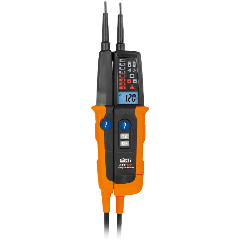
Two pole multifucntion tester with in-built LED torch · HT10 is designed to carry out the measur…
详细指标
以下为该型号的技术指标,逐表取自官方《HT10 用户手册》(英文版)TECHNICAL SPECIFICATIONS 章节、官方《HT10》数据手册、官网产品页,表内数值按官方表格原样摘录(原文为英文;括号内为单位)。厂家未列出的项目即官网与手册均未给出,未作推测。
附件
• 说明:7.3.1. Standard accessories 38
• 说明:This instrument complies with IEC/EN61010-1. For your own safety
• 说明:and to avoid damaging the instrument, you’re recommended to
• 说明:keep to the instructions contained in this manual and read carefully
附件 · all the notes preceded by the symbol ::
• CAUTION:• Depending on the internal impedance of the voltage detector there will be a different capability of indicating the presence or absence of operating voltage in case interference voltage is present • A voltage detector of relatively low internal impedance, compared to the reference value of 100kΩ, will not indicate all interference voltages having an original voltage value above the ELV level. When in contact with the parts to be tested, the voltage detector may temporarily discharge the interference voltage to a level below ELV, but voltage will be back to the original value when the voltage detector is removed • When the indication “voltage present” does not appear, it is highly recommended installing earthing equipment before proceeding • A voltage detector of relatively high internal impedance, compared to the reference value of 100kΩ, may not permit to clearly indicate the absence of operating voltage in case interference voltage is present • When the indication “voltage present” appears on a part that is expected to be disconnected from the installation, it is highly recommended confirming by other means (e.g. use of another voltage detector, visual check of the disconnected parts of the electric circuit to be tested, etc.) that there is no operating voltage on the part to be tested and to conclude that the voltage indicated by the voltage detector is an interference voltage • A voltage detector declaring two values of internal impedance has passed a performance test of detecting interference voltages and is (within technical limits) able to distinguish operating voltage from interference voltage and has a means to directly or indirectly indicate which type of voltage is present • This instrument has been designed for use in environments with pollution degree 2. • It can be used for DC and AC VOLTAGE measurements on installations of CAT IV 600V or CAT III 1000V
• 说明:The following symbols are used on the instrument:
• 说明:CAUTION - refer to the instruction manual - an improper
• 说明:use may damage the instrument or its components
• 说明:Double insulated
• 说明:DC Voltage
• 说明:AC Voltage
• 说明:Instrument suitable for carrying out measurements under
• 说明:voltage
• 说明:The instrument complies with the regulation of the TÜV
• 说明:Association for Electrical, Electronic & Information
• 说明:Technologies and with the rules of "Geprüfte Sicherheit
• CAUTION:this symbol indicates that equipment, the
• 说明:battery, and its accessories shall be subject to a separate
环境条件
• 说明:Always keep to the instructions contained in this manual:
• 说明:• When using the instrument always respect the usual safety
• 说明:regulations aimed at protecting you against dangerous electric
• 说明:currents as well as the instrument against incorrect operation
• 说明:• Do not test nor connect to any circuit exceeding the specified
• 说明:overload protection
• 说明:exceeding the limits indicated in § 7.2
• 说明:• Check the state of the internal batteries before use and replace
• 说明:them if necessary
• 说明:• Prior to usage ensure perfect instrument function (e.g. on a known
• 说明:voltage source)
• 说明:• The functionality of the instrument must be quickly checked
• 说明:before and after use by using the test probes. If the indication of
• 说明:one or more steps fails or if no functionality is verified, the
• 说明:instrument is no longer to be used
• 说明:• The different signals indicated by the instrument (including the
• 说明:ELV limit indication) must not be used for measuring purposes
• 说明:• Before using the instrument with audible indicator at locations
• 说明:with a high background noise level please evaluate if the audible
• 说明:signal is perceptible
• 说明:• Position the instrument in order to avoid hiding of visual indication
• 说明:or covering of sound transmitter
• 说明:• Check the state of the voltage source before to use the instrument
• 说明:If you expect not to use the instrument for a long period remove
环境条件 · batteries
• CAUTION:Noncompliance with the CAUTIONs and/or the instructions may damage the tester and/or its components or injure the operator
• The norm IEC/EN61010-1:Safety requirements for electrical
• 说明:equipment for measurement, control and laboratory use, Part 1:
• 说明:General requirements, defines what measuring category, usually
• called overvoltage category, is. On § 6.7.4:Measuring circuits, it says:
• 说明:(OMISSIS)
• 说明:Circuits are divided into the following measurement categories:
• 说明:• Measurement category IV is for measurements performed at the
• 说明:source of the low voltage installation
• 说明:Examples are electricity meters and measurements on primary
• 说明:overcurrent protection devices and ripple control units
• 说明:• Measurement category III is for measurements performed in the
• 说明:building installation
• 说明:Examples are measurements on distribution boards, circuit
• 说明:breakers, wiring, including cables, busbars, junction boxes,
• 说明:switches, socket-outlets in the fixed installation, and equipment
• 说明:for industrial use and some other equipment, for example,
• 说明:stationary motors with permanent connection to fixed
• 说明:installation.
• 说明:• Measurement category II is for measurements performed on
• 说明:circuits directly connected to the low voltage installation
• 说明:Examples are measurements on household appliances, portable
• 说明:tools and similar equipment.
• 说明:• Measurement category I is for measurements performed on
• 说明:circuits not directly connected to MAINS
• 说明:Examples are measurements on circuits not derived from MAINS,
• 说明:and specially protected (internal) MAINS-derived circuits. In the
• 说明:latter case, transient stresses are variable; for that reason, the
• 说明:norm requires that the transient withstand capability of the
• 说明:equipment is made known to the user
• 说明:The instrument performs the below measurements:
• 说明:• DC Voltage with 2-wire method
• 说明:• AC Voltage with 2-wire method
• 说明:• AC Voltage with 1-wire method (polarity detection)
• 说明:• AC Voltage measurement with low impedance value
• 说明:• Phase sequence indication
• 说明:• Resistance measurement
• 说明:• Continuity test with buzzer
• 说明:The measurement result is displayed with indication of the
• 说明:measuring unit both in numerical mode and on the LCD display. A
• 说明:white pointer LED is also available in order to correctly perform the
环境条件 · tests even in poorly lit environments
• 说明:The instrument has been checked from a mechanical and electrical
• 说明:point of view before shipment. Every care has been taken to make
• 说明:sure that the instrument reaches you in perfect conditions. However,
• 说明:it’s advisable to make a rapid check to detect any damage which
• 说明:may have occurred in transit. Should this be the case, enter
• 说明:immediately the usual claims with the carrier. Make sure that all the
• 说明:accessories listed in § 7.3.1 are contained in the package. In case of
• 说明:discrepancies contact Your dealer. In case of returning of the tester
环境条件 · please keep to the instructions given in § 8
• 说明:The instrument is powered by 2x1.5V alkaline batteries type AAA
• 说明:LR03. When batteries are low, a low battery indication “ ” is
环境条件 · displayed. To replace batteries please follow the instructions of § 6.2
• 说明:exceeding the limits mentioned in § 7.2 let the instrument come
• 说明:back to normal measuring conditions before using it.
环境条件 · Before starting any measurement perform the following checks
• CAUTION:• Use the instrument on a known voltage source • The " " LED switches on when a voltage above 50VAC/120VDC is applied, even if the battery is low or has been removed • Before and after the use of instrument short the L1 and L2 probes for approx. 4-6s. The below actions must be noted: ➢ All the LEDs except low impedance test switch on ➢ The audible signal will sound ➢ All segments of display and backlight switch on
环境条件
• CAUTION:• The maximum input for DC Voltage is 1000V. Do not measure higher voltages to avoid risks of electrical shocks or serious damages to the instrument • Warning LED turns ON and the buzzer sound for voltage between probes over 120V
• 说明:4). The measurement is performed only with contact of probes
• 说明:directly on metal parts of conductors
• 说明:the DC voltage value is displayed both through red LEDs
• 说明:switching on and on the display. DC symbol is displayed and “+”
• 说明:LED switches on
• 说明:voltage has an opposite direction compared to the connection
• 说明:shown in Fig. 4
• 说明:disconnected from the object under test
• 说明:display. Press and hold the H/ key in order to
• 说明:activate/deactivate the display backlight
• CAUTION:• The maximum input for AC Voltage is 1000V. Do not measure higher voltages to avoid risks of electrical shocks or serious damages to the instrument • Warning LED turns ON and the buzzer sound for voltage between probes over 50V
• 说明:5). The measurement is performed only with contact of probes
• 说明:directly on metal parts of conductors
• 说明:and the AC voltage value is displayed both through red LEDs
• 说明:switching on and on the display. AC symbol is displayed
• 说明:measurement is displayed, and an acoustic signal is emitted
• 说明:disconnected from the object under test
• 说明:turn on This is not a device problem
• 说明:and hold the H/ key in order to activate/deactivate the display
• 说明:backlight
• CAUTION:• The maximum input for AC Voltage is 1000V. Do not measure higher voltages to avoid risks of electrical shocks or serious damages to the instrument • Warning LED turns ON and the buzzer sound for voltage between probes over 50V • This function is particularly useful for testing installations. Due to the lowered internal impedance, capacitive voltage effects are suppressed. The reading shows the actual voltage applied. Similarly, measuring phase (L1) on earth wire (PE) may trigger fault-current circuit breakers (RCD)
• 说明:6). The measurement is performed only with contact of probes
• 说明:directly on metal parts of conductors
• 说明:measurement is displayed and an acoustic signal is emitted
• 说明:applied voltage is displayed both through red LEDs switching
• 说明:on and on the display. AC symbol is displayed. The LED for low
• 说明:impedance test (see Fig. 2 – part 2) switches on
• 说明:disconnected from the object under test
• 说明:turn on. This is not a device problem
• 说明:display. Press and hold the H/ key in order to
• 说明:activate/deactivate the display backlight
• CAUTION:• The maximum


 客服








 粤公网安备44030902003758