是德科技 | KEYSIGHT
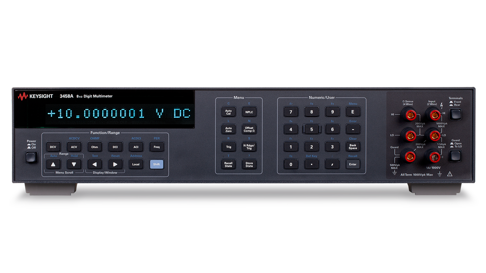
3458A 万用表 详细指标
Benchtop Digital Multimeters
一、Settling Specifications
条件:1. Applies for 1 kΩ unbalance in the LO lead and ± 0.1% of the frequency currently set for LFREQ.
2. For line frequency ±1%, ACNMR is 40 dB for NPLC ≥ 1, or 55 dB for NPLC ≥ 100. For line frequency ±5%, ACNMR is 30 dB for
Integration time in number power line cycles (NPLC, log scale)
Range Multiplier 0.1 V X20 1 V X2
10 V X1
100 V X2
1000 V X1
For RMS noise error, multiply the RMS noise result from the graph by the multiplier in the chart. For peak noise error, multi ply
NPLC Aperture Digits Bits Readings / s
条件:1. For PRESET; DELAY 0; DISP OFF; OFORMAT DINT; ARANGE OFF.
2. Aperture is selected independent of line frequency (LFREQ). These apertures are for 60 Hz NPLC values where 1 NPLC = 1 /
LFREQ. For 50 Hz and NPLC indicated, aperture will increase by 1.2 and reading rates will decrease by 0.833.
3. For OFORMAT SINT.
A-zero off A-zero on 0.0001 1.4 μs 4.5 16 100,000 3 4,130 0.0006 10 μs 5.5 18 50,000 3,150 0.01 167 μs 2 6.5 21 5,300
930
0.1 1.67 ms 2 6.5 21 592
245
1 16.6 ms 2 7.5 25 60
29.4
100 8.5 28 36 / min
18 / min
1000 8.5 28 3.6 / min
1.8 min
Temperature Coefficient (Auto-Zero OFF)
For a stable environment ±1 ºC add the following additional error for AZERO OFF
Range Error 100 mV – 10 V 5 μV/ºC 100 V – 1000 V
500 μV/ºC
Rated Input Non-Destructive
条件:1. > 1010 Ω LO to guard with guard open.
2. > 1012 Ω guard to Earth.
HI to LO ±1000 V pk
±1200 V pk
LO to Guard1 ±200 V pk
±350 V pk
Guard to Earth2 ±500 V pk
±1000 V pk
Terminal material: gold-plated tellurium copper
Input leakage current <
20 pA at 25 ºC
条件:1. Current source is ±3% absolute accuracy.
2. Additional error from Tcal or last ACAL ±1 ºC .
3. Additional error from Tcal ±5 ºC.
4. Measurement is computed from 10 MΩ in parallel with input.
1. Specifications are for PRESET;NPLC 100; OCOMP ON; OHMF.
2. Tcal ±1 ºC.
3. Specifications for 90- day, 1 year, and 2 years are within 24 hours and ±1 ºC of the last ACAL; Tcal ±5 ºC. Add 3 ppm of reading
10 Ω 12.00000 10 μΩ 10 mA 0.1 V 12 V 20 Ω 0.01 V 3 + 1 1 +
1
100 Ω 120.00000 10 μΩ 1 mA 0.1 V 12 V 200 Ω 0.01 V 3 + 1 1 +
1
1 kΩ 1.2000000 100 μΩ 1 mA 1.0 V 12 V 150 Ω 0.1 V 3 + 0.1 1 +
0.1
10 kΩ 12.000000 1 mΩ 100 μA 1.0 V 12 V 1.5 kΩ 0.1 V 3 + 0.1 1 +
0.1
100 kΩ 120.00000 10 mΩ 50 μA 5.0 V 12 V 1.5 kΩ 0.5 V 3 + 0.1 1 +
0.1
1 MΩ 1.2000000 100 mΩ 5 μA 5.0 V 12 V 1.5 kΩ 3 + 1 1 +
1
10 MΩ 12.000000 1 Ω 500 nA 5.0 V 12 V 1.5 kΩ 20 + 20 5 +
2
100 MΩ 4 120.00000 10 Ω 500 nA 5.0 V 5 V 1.5 kΩ 100 + 20 25 +
2
1 GΩ4 1.2000000 100 Ω 500 nA 5.0 V 5 V 1.5 kΩ 1000 + 20 1
2
Accuracy
1 (ppm of Reading + ppm of Range)
Range 24-Hour 2 90 Day 3 1 Year 3 2 Year
3
10 Ω 5 + 3 15 + 5 15 + 5 20 +
10
100 Ω 3 + 3 10 + 5 12 + 5 20 +
10
1 kΩ 2 + 0.2 8 + 0.5 10 + 0.5 15 +
1
10 kΩ 2 + 0.2 8 + 0.5 10 + 0.5 15 +
1
100 kΩ 2 + 0.2 8 + 0.5 10 + 0.5 15 +
1
1 MΩ 10 + 1 12 + 2 15 + 2 20 +
4
10 MΩ 50 + 5 50 + 10 50 + 10 75 +
10
100 MΩ 500 + 10 500 + 10 500 + 10 0.1% +
10
1 GΩ 0.5% + 10 0.5% + 10 0.5% + 10 1% +
10
additional error for factory traceability of 10 kΩ to US NIST. Traceability is the absolute error relative to National Standards
条件:accuracy. 24 Hour: 50 mΩ. 90 Day: 150 mΩ. 1 Year: 250 mΩ. 2 Year: 500 mΩ.
For two-wire ohms (OHM) accuracy, add the following offset errors to the four-wire ohms (OHMF)
Integration time in number power line cycles (NPLC, log scale)
二、Settling Specifications
条件:current range. Preprogrammed settling delay times are for < 200 pF external circuit capacitance.
1. For PRESET;DELAY 0; DISP OFF; OFORMAT DINT; ARANGE OFF.
2. Ohms measurements at rates < NPLC 1 are subject to potential noise pickup. Care must be taken to provide adequate shielding
LFREQ. For 50 Hz and NPLC indicated, aperture will increase by 1.2 and reading rates will decrease by 0.833.
4. For OFORMAT SINT.
For the first reading error following the range change, add the total
90-day measurement error for the
NPLC
2 Aperture Digits Readings / s
A-zero off A-zero on 0.0001 1.4 μs 4.5 100,000 4 4,130 0.0006 10 μs 5.5 50,000 3,150 0.01 167 μs 3 6.5 5,300
930
For OHMF or OCOMP ON, the maximum reading rates will be slower.
and guarding to maintain measurement accuracies. 3. Aperture is selected independent of line frequency (LFREQ). These apertures are for 60 Hz NPLC values where 1 NPLC =
1 /
Measurement Consideration
Keysight recommends using a PTFE (Polytetrafluoroethylene) cable or another high-impedance, low-
Rated Input Non-Destructive
HI to LO ±1000 V pk
±1000 V pk
HI & LO sense to LO ±200 V pk
±350 V pk
LO to guard ±200 V pk
±350 V pk
Guard to Earth ±500 V pk
±1000 V pk
Range Multiplier 10 Ω & 100 Ω X10 1 kΩ 10 100 kΩ X1
1 MΩ X1.5
10 MΩ X2
100 MΩ X120
1 GΩ X1200
For RMS noise error, multiply the RMS noise result from the graph by the multiplier in the chart. For peak noise error, multi ply
Temperature Coefficient (Auto-Zero OFF)
For a stable environment
±1 ºC, add the following additional error for AZERO OFF. (ppm of range)/ ºC
Range Error 10 Ω 50 100 Ω 50 1 kΩ
5
Temperature Coefficient (ppm of Reading + ppm of Range) / ºC
条件:1. Additional error from Tcal or Last ACAL ±1 ºC.
2. Additional error from Tcal ±5 ºC.
3. Specifications are for PRESET;NPLC 100.
4. Tcal ±1 ºC.
5. Specifications for 90- day, 1 year, and 2 year are within 24- hours and ± 1 ºC of last ACAL; Tcal ± 5 ºC.
Without ACAL 1 With ACAL
2
100 nA 120.000 1 pA 545.2 kΩ 0.055 V 10 + 200 2 +
50
1 μA 1.200000 1 pA 45.2 kΩ 0.045 V 2 + 20 2 +
5
10 μA 12.000000 1 pA 5.2 kΩ 0.055 V 10 + 4 2 +
1
100 μA 120.00000 10 pA 730 Ω 0.075 V 10 + 3 2 +
1
1 mA 1.2000000 100 pA 100 Ω 0.100 V 10 + 2 2 +
1
10 mA 12.000000 1 nA 10 Ω 0.100 V 10 + 2 2 +
1
100 mA 120.00000 10 nA 1 Ω 0.250 V 25 + 2 2 +
1
1 A 1.0500000 100 nA 0.1 Ω < 1.5 V 25 + 3 2+
2
Accuracy
3 (ppm of Reading + ppm of Range)
Range 24-Hour 4 90 Day 5 1 Year 5 2 Year
5
100 nA6 10 + 400 30 + 400 30 + 400 35 +
400
1 μA6 10 + 40 15 + 40 20 + 40 25 +
40
10 μA6 10 + 7 15 + 10 20 + 10 25 +
10
100 μA 10 + 6 15 + 8 20 + 8 25 +
8
1 mA 10 + 4 15 + 5 20 + 5 25 +
5
10 mA 10 + 4 15 + 5 20 + 5 25 +
5
100 mA 25 + 4 30 + 5 35 + 5 40 +
5
1 A 100 + 10 100 + 10 110 + 10 115 +
10
Add 5 ppm of reading additional error for factory traceability to US NIST. Traceability error is the sum of the
10 V and 10 k Ω
traceability values.
6. Typical accuracy.
三、Settling Specifications
条件:times can be affected by source impedance and cable dielectric absorption characteristics.
For first reading or range change error, add
0.001% of input current step additional error. Reading settling
Integration time in number power line cycles (NPLC, log scale)
条件:For RMS noise error, multiply RMS noise result from graph by multiplier in chart.
1. For PRESET; DELAY 0; DISP OFF; OFORMAT DINT; ARANGE OFF.
2. Aperture is selected independent of line frequency (LFREQ). These apertures are for 60 Hz NPLC values where 1 NPLC = 1
/LFREQ. For 50 Hz and NPLC indicated, aperture will increase by 1.2 and reading rates will decrease by 0.833.
Range Multiplier 100 nA X100 1 μA X10
10 μA to 1 A X1
For peak noise error, multiply RMS noise error by
3.
NPLC Aperture Digits Readings / Second 0.0001 1.4 μs 4.5 2,300 0.0006 10 μs 5.5 1,350 0.01 1.67 μs 2 6.5
157
Rated Input Non-Destructive
HI to LO ±1.5 A pk <
1.25 A rms
LO to guard ±200 V pk
±350 V pk
Guard to Earth ±500 V pk
±1000 V pk
Measurement Considerations
条件:current measurements. Current measurements at rates < NPLC 1 are subject to potential noise pickup.
Care must be taken to provide adequate shielding and guarding to maintain measurement accuracies.
Keysight recommends using PTFE cable or other high impedance, low dielectric absorption cable for low
条件:functions will then apply the chosen method for subsequent measurements.
can help you choose the technique best suited to your specific measurement needs.
The Keysight 3458A supports three techniques for measuring true rms AC voltage, each offering unique
capabilities. The desired measurement technique is selected through the SETACV command. The ACV
The following section provides a brief description of the three operation modes and a summary table that
Operation Modes Descriptions
SETACV SYNC Synchronously sub-sampled computed true rms technique.
This technique provides excellent linearity and the most accurate measurement results. It
requires that the input signal be repetitive (not random noise, for example). The bandwidth in
this mode is from 1 Hz to 10 MHz.
SETACV ANA Analog computing true rms conversion technique
This is the measurement technique at power-up or following an instrument reset. This mode
works well with any signal within its
10 Hz to 2 MHz bandwidth and provides the fastest
SETACV RNDM Random sampled computed true rms technique
条件:wideband noise measurements. The bandwidth in this mode is from 20 Hz to 10 MHz.
This technique again provides excellent linearity; however, the overall accuracy is the lowest
of the three modes. It does not require a repetitive input signal and is therefore well suited to
Synchronous sub-sampled 1 Hz – 10 MHz 0.010% Yes 0.025
10
Analog 10 Hz – 2 MHz 0.03% No 0.8
50
Random sampled 20 Hz – 10 MHz 0.1% no 0.025
45
条件:1. Additional error beyond ± 1ºC, but within + 5 ºC of last ACAL. For ACBAND > 2MHz, use 10 mV range temperature coefficient
for all ranges. 2. Specifications apply full scale to 10% of full scale, DC < 10% of AC sine wave input, crest factor = 1.4, and PRESET. Within 24- hours and ± 1 ºC of last ACAL Lo to guard switch on. Peak (AC + DC) input limited to 5x full scale for all ranges in ACV function. Add 2ppm of reading additional error for factory traceability of 10 V DC to US NIST.
3. LFILTER ON recommended.
Temperature Coefficient1
(% of Reading + % of Range) / ºC 10 mV 12.00000 10 nV 1 MΩ ±15% with < 140 pF 0.002 + 0.02 100 mV 120.00000 10 nV 1 MΩ ±15% with < 140 pF 0.001 + 0.0001 1 V 1.2000000 100 nV 1 MΩ ±15% with < 140 pF 0.001 +
0.0001
10 V 12.000000 1 μV 1 MΩ ±2% with < 140 pF 0.001 +
0.0001
100 V 120.00000 10 μV 1 MΩ ±2% with < 140 pF 0.001 +
0.0001
1000 V 700.0000 100 μV 1 MΩ ±2% with < 140 pF 0.001 +
0.0001
24-hour to 2 year (% of reading + % of range)
40 Hz
40 Hz to 3
1 kHz
1 kHz to 3
20 kHz
20 kHz to 3
50 kHz
50 kHz to
100 kHz
100 kHz to
300 kHz
300 kHz to
1 MHz
1 MHz to
2 MHz
10 mV 0.03 + 0.03 0.02 + 0.011 0.03 + 0.011 0.1 + 0.011 0.5 + 0.011 4.0 +
0.02
100 mV – 10V 0.007 + 0.004 0.007 + 0.002 0.014 + 0.002 0.03 + 0.002 0.08 + 0.002 0.3 + 0.01 1 + 0.01 1.5 +
0.01
100 V 0.02 + 0.004 0.02 + 0.002 0.02 + 0.002 0.035 + 0.002 0.12 + 0.002 0.4 + 0.01 1.5 +
0.01
1000 V 0.04 + 0.004 0.04 + 0.002 0.06 + 0.002 0.12 + 0.002 0.3 +
0.002
Range 45 Hz to 100 kHz 100 kHz to 1 MHz 1 MHz to 4 MHz 4 MHz to 8 MHz
8 MHz to 10 MHz
10 mV 0.09 + 0.06 1.2 + 0.05 7 + 0.07 20 +
0.08
100 mV – 10V 0.09 + 0.06 2.0 + 0.05 4 + 0.07 4 + 0.08 15 +
0.1
• Following
4- hour warm -up
• Within
10 min and ±0.5 ºC of the reference measurement
• 45 Hz to 20 kHz, sine wave input
• Within
±10% of the reference voltage and frequency
条件:1. Additional error beyond ±1 ºC, but within ±5 ºC of last ACAL (% of Range)/ ºC. For ACBAND > 2 MHz, use 10 mV range
For ACDCV accuracy, apply the following additional error to the ACV accuracy (% of range)
Range ACBAND ≤ 2 MHz ACBAND > 2 MHz Temperature Coefficient
1
100 mV – 1000V 0.008 0.09
0.0025
Range ACBAND ≤ 2 MHz ACBAND > 2 MHz Temperature Coefficient
1
100 mV – 1000V 0.07 0.7
0.25
条件:2. Flatness error, including instrument loading.
3. Reading time is the sum of the second / reading shown for your configuration. The tables will yield the slowest reading rate for
your configuration. Actual reading rates may be faster. For DELAY- 1; ARANGE OFF.
Apply the following additional errors as appropriate to your measurement setup. (% of reading)
Source 0 – 1 MHz 1 – 4 MHz 4 – 8 MHz 8 – 10 MHz Crest Factor Resolution Multiplier
1
0 Ω 0 2 5 5 1 – 2 (Resolution in %) x
1
50 Ω terminated 0.003 0 0 0 2 – 3 (Resolution in %) x
2
75 Ω terminated 0.004 2 5 5 3 – 4 (Resolution in %) x
3
50 Ω 0.005 3 7 10 4 – 5 (Resolution in %) x
5
ACBAND Low Maximum Second / Reading % Resolution Maximum Second / Reading
1 – 5 Hz 6.5 0.001 – 0.005
32
5 – 20 Hz 2.0 0.005 – 0.01
6.5
20 – 100 Hz 1.2 0.01 – 0.05
3.2
100 – 500 Hz 0.32 0.05 – 0.1
0.64
> 500 Hz 0.02 0.1 – 1
0.32
四、Settling Specifications
For 1 kΩ imbalance in LO lead, >
90 dB, DC to 60 Hz.
For outside Tcal ±5 ºC, add the following error. (% of reading)/ ºC
Range 2 – 4 MHz
4 – 10 MHz
Rated Input Non-Destructive
HI to LO ±1000 V pk
±1200 V pk
LO to guard ±200 V pk
±350 V pk
Guard to Earth ±500 V pk
±1000 V pk
Analog Mode (ACV Function, SETACV ANA)
Range Full Scale Maximum Resolution Input Impedance Temperature Coefficient
1
(% of Reading + % of Range)/ ºC 10 mV 12.00000 10 nV 1 MΩ ± 15% with < 140 pF 0.003 + 0.006 2 100 mV 120.0000 100 nV 1 MΩ ± 15% with < 140 pF 0.002 + 0.0 1 V 1.200000 1 μV 1 MΩ ± 15% with < 140 pF 0.002 +
0.0
10 V 12.00000 10 μV 1 MΩ ± 2% with < 140 pF 0.002 +
0.0
100 V 120.0000 100 μV 1 MΩ ± 2% with < 140 pF 0.002 +
0.0
1000 V 700.000 1 mV 1 MΩ ± 2% with < 140 pF 0.002 +
0.0
24-Hour to 2 Year (% of Reading + % of Range)
20 Hz
100 Hz
100 Hz
50 kHz
50 kHz
250 kHz
250 kHz
1 MHz
1 MHz
to 2 MHz 10 mV 0.4+0.32 0.15+0.25 0.06+0.25 0.02+0.25 0.15+0.25 0.7+0.35 4+0.7 100 mV – 10 V 0.4+0.02 0.15+0.02 0.06+0.01 0.02+0.01 0.15+0.04 0.6+0.08 2+0.5 3+0.6 5+2
10+5
100 V 0.4+0.02 0.15+0.02 0.06+0.01 0.03+0.01 0.15+0.04 0.6+0.08 2+0.5 3+0.6
5+2
1000 V 0.42+0.03 0.17+0.03 0.08+0.02 0.06+0.02 0.15+0.04
0.6+0.2
For ACDCV accuracy, apply the following additional error to the ACV accuracy (% of reading + % of
DC < 10% of AC Voltage DC >
10% of AC Voltage
条件:1. Additional error beyond ±1 ºC but within ±5 ºC of the last ACAL.
2. Specifications apply full scale to ¼ full scale.
3. Specifications apply full scale to 1/20 full scale, sinewave input, crest factor = 1.4, and PRESET. Within 24 hours and ±1 ºC of
4. Additional error beyond ±1 ºC but within ±5 ºC of the last ACAL. (% of Reading + % of Range)/ ºC
10 mV 0.0 + 0.2 0 + 0.015 0.15 + 3 0 +
0.06
100 mV – 1000V 0.0 + 0.02 0 + 0.001 0.15 + 0.25 0 +
0.007
the last ACAL. Lo to guard switch on. Maximum DC is limited to 400 V in ACV functions. Add
2 ppm of reading additional error
for factory traceability of 10 V DC to US NIST.
Signal Frequency
10 Hz – 1 kHz
1 – 10 kHz
> 10 kHz
Crest Factor Additional Error 1 – 2 0 2 – 3 0.15 3 – 4
0.25
条件:1. For DELAY- 1; ARANGE OFF. For DELAY 0; NPLC .1, unspecified reading rates of greater than 500 / second are possible.
For 1 kΩ imbalance in LO lead, >
90 dB, DC – 60 Hz.
五、Settling Specifications
For the first reading or range change error using default delays, add
0.01% of the input step additional
error. The following data applies for DELAY
0.
功能 ACBAND 低 DC Component 建立时间
ACV ≥ 10 kHz DC < 10% AC
0.5 sec to 0.01%
DC > 10% AC
0.9 sec to 0.01%
ACDC 10 Hz – 1 kHz
0.5 second to 0.01%
1 kHz – 10 kHz
0.08 sec to 0.01%
≥ 10 kHz
0.015 sec to 0.01%
Rated Input Non-Destructive
HI to LO ±1000 V pk
±1200 V pk
LO to guard ±200 V pk
±350 V pk
Guard to Earth ±500 V pk
±1000 V pk
Random Sampled Mode (ACV Function, SETACV RNDM)
条件:1. Additional error beyond ±1 ºC, but within ±5 ºC of last ACAL. For ACBAND > 2 MHz, use 10 mV range temperature coefficient
Range Full Scale Maximum Resolution Input Impedance Temperature Coefficient
1
(% of Reading + % of Range)/ ºC 10 mV 12.00000 1 μV 1 MΩ ± 15% with < 140 pF 0.002 + 0.02 100 mV 120.0000 10 μV 1 MΩ ± 15% with < 140 pF 0.001 + 0.00001 1 V 1.200000 100 μV 1 MΩ ± 15% with < 140 pF 0.001 +
0.00001
10 V 12.00000 1 mV 1 MΩ ± 2% with < 140 pF 0.001 +
0.00001
100 V 120.0000 10 mV 1 MΩ ± 2% with < 140 pF 0.001 +
0.00001
1000 V 700.000 100 mV 1 MΩ ± 2% with < 140 pF 0.001 +
0.00001
24-hour to 2 year (% of reading + % of range)
ACBAND ≤ 2 MHz ACBAND >
2 MHz
100 kHz
100 kHz to
300 kHz
300 kHz to
1 MHz
1 MHz to
2 MHz
20 Hz to
100 kHz
100 kHz to
1 MHz
1 MHz to
4 MHz
4 MHz to
8 MHz
8 MHz to
10 MHz
10 mV 0.5+0.02 4+0.02 0.1+0.05 1.2+0.05 7+0.07
20+0.08
100 mV-10 V 0.08+0.002 0.3+0.01 1+0.01 1.5+0.01 0.1+0.05 2+0.05 4+0.07 4+0.08
15+0.1
100 V 0.12+0.002 0.4+0.01 1.5+0.01
0.12+0.002
条件:For ACDCV accuracy, apply the following additional error to the ACV accuracy (% of range).
DC ≤ 10% of AC Voltage DC >
10% of AC Voltage
≤ 2 MHz
> 2 MHz
≤ 2 MHz
> 2 MHz
10 mV 0.09 0.09 0.03 0.7 0.7
0.18
100 mV - 1 kV 0.008 0.09 0.0025 0.07 0.7
0.025
条件:Apply the following additional errors as appropriate to your measurement setup (% of reading).
1. Specifications apply from full scale to 5% of full scale, DC < 10% of AC, sine wave input, crest factor = 1.4, and PRESET.
2. Additional error beyond ±1 ºC but within ±5 ºC of the last ACAL. (% of reading)/ ºC. For ACBAND > 2 MHz, use a 10 mV range
temperature coefficient for all ranges. 3. Flatness error, including instrument loading.
Source R 0 – 1 MHz 1 – 4 MHz 4 – 8 MHz
8 – 10 MHz Crest Factor Resolution Multiplier
0 Ω 0 2 5 5 1 – 2 (Resolution in %) x
1
50 Ω terminated 0.003 0 0 0 2 – 3 (Resolution in %) x
3
75 Ω terminated 0.004 2 5 5 3 – 4 (Resolution in %) x
5
50 Ω 0.005 3 7 10 4 – 5 (Resolution in %) x
8
Within 24 hours and ±1 ºC of the last ACAL. LO to guard switch on. Add
2 ppm of reading additional error for factory traceabi lity
of 10V DC to US NIST. Maximum DC is limited to 400V in ACV function.
For 1 kΩ imbalance in LO lead, >
90 dB, DC – 60 Hz
条件:1. For DELAY -1; ARANGE OFF. For DELAY 0 in ACV, the reading rated are identical to ACDCV.
% Resolution ACV ACDCV 0.1 – 0.2 40 39 0.2 – 0.4 11 9.6 0.4 – 0.6 2.7
2.4
For outside Tcal ±5 ºC add the following error (% of reading)/ ºC
Range 2 – 4 MHz
4 – 10 MHz
六、Settling Specifications
For the first reading or range change error using default delays, add
0.01% of the input step additional
error. The following data applies for DELAY
0.
ACV DC < 10% AC
0.5 sec to 0.01%
DC < 10% AC
0.9 sec to 0.01%
Rated Input Non-Destructive
HI to LO ±1000 V pk
±1200 V pk
LO to guard ±200 V pk
±350 V pk
Guard to Earth ±500 V pk
±1000 V pk
Range Full Scale Maximum Resolution Shunt Resistance Burden Voltage
(% of Reading + % of Range)/ ºC 100 μA 120.0000 100 pA 730 Ω 0.1 V 0.002 + 0 1 mA 1.200000 1 nA 100 Ω 0.1 V 0.002 + 0 10 mA 12.00000 10 nA 10 Ω 0.1 V 0.002 +
0
100 mA 120.0000 100 nA 1 Ω 0.25 V 0.002 +
0
1 A 1.050000 1 μA 0.1 Ω < 1.5 V 0.002 +
0
24-hour to 2 year (% reading + % range)
Range 10 Hz to 20 Hz
20 Hz to
45 Hz
45 Hz to
100 Hz
100 Hz to
5 kHz
5 kHz to
20 kHz to
50 kHz to
100 μA 4 0.4+0.03 0.15+0.03 0.06+0.03
0.06+0.03
1 mA – 100 mA 0.4+0.02 0.15+0.02 0.06+0.02 0.03+0.02 0.06+0.02 0.4+0.04
0.55+0.15
1 A 0.4+0.02 0.16+0.02 0.08+0.02 0.1+0.02 0.3+0.02
1+0.04
条件:For ACDCI accuracy, apply the following additional error to the ACI accuracy (% of reading + % of range).
1. Additional error beyond ±1 ºC, but within ±5 ºC of last ACAL.
2. Specifications apply full scale to 1/20 full scale, for sine wave inputs, crest factor = 1.4, and following PRESET within 24- hours
3. Typical performance.
4. 1 kHz maximum on the 100 μA range.
5. Additional error beyond ±5 ºC of last ACAL (% of reading + % of range)/ ºC.
DC ≤ 10% of AC Accuracy Temperature Coefficient 5 DC > 10% of AC Accuracy Temperature Coefficient
5
0.005 + 0.02 0.0 + 0.001 0.15 + 0.25 0.0 +
0.007
and ±1 ºC of last ACAL. Add
5 ppm of reading additional error for factory traceability to US NIST. Traceability is the sum of the
10 V and 10 kΩ traceability values.
Signal Frequency
10 Hz – 1 kHz
1 – 10 kHz
> 10 kHz
Crest Factor Additional Error 1 – 2 0 2 – 3 0.15 3 – 4
0.25
ACBAND Low NPLC ACI ACDCI
条件:1. For DELAY- 1; ARANGE OFF. For DELAY 0; NPLC .1, unspecified reading rates of greater than 500/second are possible.
七、Settling Specifications
For the first reading or range change error using default delays, add
0.01% of input step additional error
for the 100 μA to 100 mA ranges. For the 1 A range, add
0.05% of the input step additional error. The
following data applies for DELAY
0.
功能 ACBAND 低 DC Component 建立时间
ACI ≥ 10 Hz DC < 10% AC
0.5 sec to 0.01%
DC > 10% AC
0.9 sec to 0.01%
ACDCI 10 Hz – 1 kHz
0.5 sec to 0.01%
1 kHz – 10 kHz
0.08 sec to 0.01%
≥ 10 kHz
0.015 sec to 0.01%
Rated Input Non-Destructive
I to LO ±1.5 A pk <
1.25 A rms
LO to guard ±200 V pk
±350 V pk
Guard to Earth ±500 V pk
±1000 V pk
条件:1. The source of frequency measurements and the measurement input coupling are determined by FSOURCE command.
2. Gate dependent. See ACI for specific range impedance values.
Frequency range 1 Hz – 10 MHz
1 Hz – 100 kHz
Period range 1 sec – 100 ns
1 sec – 10 μs
Input signal range 700 V rms – 1 mV rms
1 A rms – 10 μA rms
Input impedance 1 MΩ ± 15% with < 140 pF 0.1 – 730 Ω
2
Range
24 Hour – 2 Year (0 ºC – 55 ºC)
1 Hz – 40 Hz (1 s – 25 ms)
0.05% of reading
40 Hz – 100 MHz (25 ms – 100 ns)
0.01% of reading
条件:1. Gate time is determined by the specific measurement resolution.
2. The maximum input specified to fixed range operation. For auto range, the maximum speed is 30 readings/second for ACBAND
Resolution Gate Time 1 Readings/Second
2
≥ 1 kHz. Actual reading speed is the longer of 1 period of the input, the chosen gate time, or the default reading time- out of 1.2
Time Base 10 MHz ± 0.01%
0 ºC to 55 ºC
Level Trigger
± 500% of range in 5% steps
Selectable
75 kHz low pass trigger filter
条件:below to help you select the setup best suited to your specific application.
The Keysight 3458A supports three independent methods for signal digitizing. Each method is discussed
This mode of digitizing allows signal acquisition at rates from 0.2 readings/sec at
28 bits resolution to 100 k readings/sec at 16 bits. Arbitrary sample apertures
from 500 ns to 1 second are selectable with 100 ns resolution. Input voltage
ranges cover
100 mV to 1000 V full scale. Input bandwidth varies from 30 kHz to
150 kHz depending on the measurement range.
DSAC Direct sampling AC coupled measurement technique
In these modes the input is sampled through a track/hold with a fixed
2 ns
aperture which yields a
16-bit resolution result. The sample rate is selectable from
6000 sec/sample to 20 μs/sample with 100 ns resolution. Input voltage ranges
cover
10 mV peak to 1000 V peak full scale. The input bandwidth is limited to 12
SSAC Sub-sampling (effective time sampling) AC coupled
These techniques implement synchronous sub-sampling of a repetitive input
signal through a track/hold with a 2 ns sample aperture which yields a
16-bit
resolution result. The effective sample rate is settable from 6000 sec/sample to 10
ns/sample with 10 ns resolution. Sampled data can be time ordered by the
instrument and output to the GPIB. Input voltage ranges cover
10 mV peak to
1000 V peak full scale. The input bandwidth is limited to 12 MHz.
Technique 功能输入带宽 Best 精度采样率
Standard DCV DC – 150 kHz 0.00005 – 0.01%
100 k / sec
Direct-sampled DSDC / DSAC DC – 12 MHz 0.02%
50 k / sec
Sub-sampled SSDC / SSAC DC – 12 MHz 0.02%
100 M / sec (effective)
Standard DC Volts Digitizing (DCV Function)
Range Input Impedance Offset Voltage
1 Typical Bandwidth Settling Time To 0.01% of Step
100 mV > 1010 Ω < 5 μV 80 kHz
50 μs
1 V > 1010 Ω < 5 μV 150 kHz
20 μs
10 V > 1010 Ω < 5 μV 150 kHz
20 μs
100 V 10 MΩ < 500 μV 30 kHz
200 μs
1000 V 10 MΩ < 500 μV 30 kHz
200 μs
DC Performance 0.005 % of reading + offset
1
最大值采样率 (见 DCV · More Data)
Readings / Second Resolution Aperture 100 k 15 bits 0.8 μs 100 k 16 bits 1.4 μs 50 k 18 bits
6.0 μs
条件:1. ±1 ºC of an AZERO or within 24- hours and ±1 ºC of last ACAL.
2. < 125 ns variability between multiple 3458As.
Dynamic Performance 100 mV, 1 V, 10 V ranges aperture =
6 μs
Test Input (2 x Full Scale pk-pk) Result
DFT-harmonics 1 kHz <
-96 dB
DFT-spurious 1 kHz <
-100 dB
Differential non-linearity dc <
0.003% of range
Signal-to-noise ratio 1 kHz >
96 dB
Direct and sub-Sampled Digitizing (DSDC, DSAC, SSDC, and SSAC Functions)
Range 1 Input Impedance Offset Voltage
2 Typical Bandwidth
10 mV 1 MΩ with 140 pF < 50 μV
2 MHz
100 mV 1 MΩ with 140 pF < 90 μV
12 MHz
1 V 1 MΩ with 140 pF < 800 μV
12 MHz
10 V 1 MΩ with 140 pF < 8 mV
12 MHz
100 V 1 MΩ with 140 pF < 80 mV 12 MHz
3
1000 V 1 MΩ with 140 pF < 800 mV 2 MHz
3
DC to 20 kHz Performance
0.02% of reading + offset
2
条件:1. Maximum DC voltage limited to 400 V DC in DSAC or SSAC functions.
2. ±1 ºC and within 24- hours of last ACAL ACV.
3. Limited to 1 x 10 8 V- Hz product.
4. Effective sample rate is determined by the smallest time increment used during synchronous sub- sampling of the repetitive
SSDC, SSAC 100 M (effective)
16 bits
input signal, which is
10 ns.
Dynamic Performance 100 mV, 1 V, 10 V ranges
50,000 Samples/sec
Test Input (2 x Full Scale pk-pk) Result
DFT-harmonics 20 kHz <
-90 dB
DFT-harmonics 1.005 MHz <
-60 dB
DFT-spurious 20 kHz <
-90 dB
Differential non-linearity 20 kHz <
0.005% of range
Signal-to-noise ratio 20 kHz >
66 dB
条件:1. < 25 ns variability between multiple 3458As.
Jitter: <
100 ps, for 1 MHz full-scale input
以上指标摘自厂家官方数据手册,完整定义、测试条件与保证值口径以手册为准。完整指标、测试条件与定义口径请见产品页「软件和手册 | 白皮书」栏目中的官方数据手册。
是德科技 | KEYSIGHT · onetest 仪器资源库


 客服







 粤公网安备44030902003758