是德科技 | KEYSIGHT
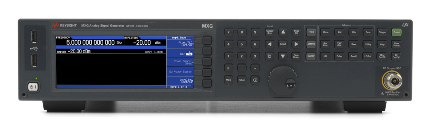
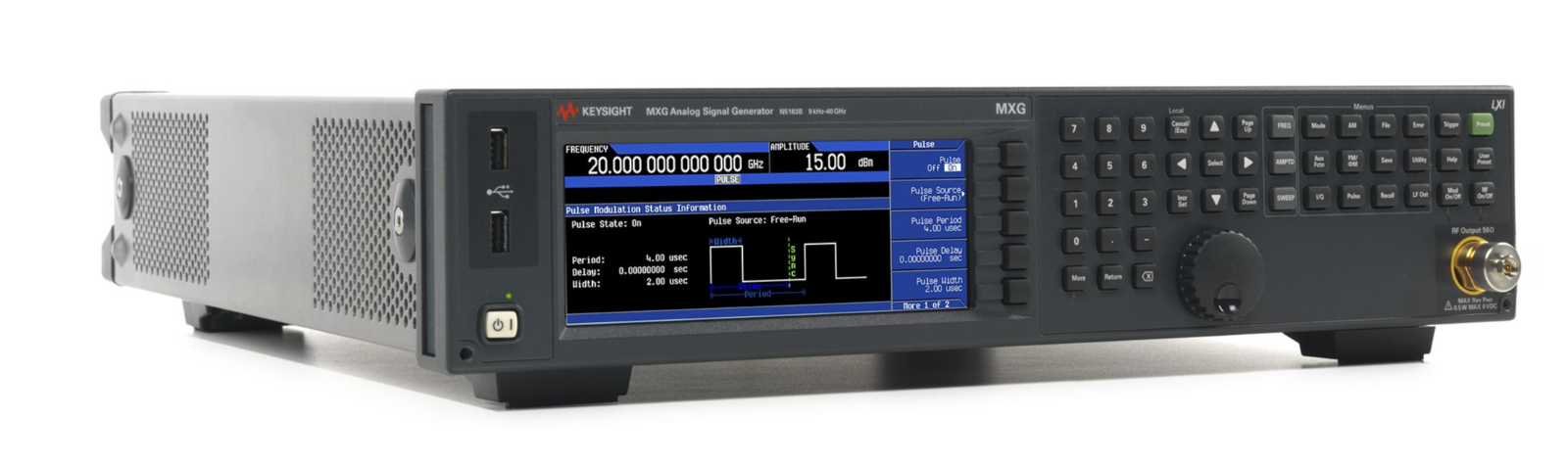
XG5系列N5183B 9 kHz 至13/20/31.8/44GHz 模拟信号发生器 详细指标
模拟信号发生器
条件:Phase offset Adjustable in nominal 0.1° increments
greater. 2 For export control purposes CW switching speed to within 0.05% of final frequency is 190 µs (meas). 3 For export control purposes CW switching speed to within 0.05% of final frequency is > 400 µs (nom) below 20 GHz and 600 µs (nom) above 20 GHz.
4 Specifications apply when status register updates are off.
Option 513
9 kHz to 13 GHz
Option 520
9 kHz to 20 GHz
Option 532
9 kHz to 31.8 GHz
Option 532
9 kHz to 40 GHz
Frequency Switching Speed
1, () = Typical
CW Mode Standard Option UNZ 2, 4 Option UZ2 3
4
SCPI mode (≤ 5 ms) ≤ 1.15 ms (≤ 750 μs) <
1.65 ms (1 ms)
List/step sweep mode (≤ 5 ms) ≤ 900 μs (≤ 600 μs) <
1.4 ms (850 μs)
1 Time from receipt of SCPI command or trigger signal to within 0.1 ppm of final frequency or within
100 Hz, whichever is
Accuracy ± Aging Rate ± Temperature Effects ± Line Voltage Effects
Internal time base reference oscillator aging rate 5 < ± 1 ×10⁻⁷/year
6
< ± 5 ×10⁻¹⁰/day after
30 days
Initial achievable calibration accuracy ± 4 ×10⁻⁸ or
± 40 ppb
Adjustment resolution < 1 x
10-10 (nom)
Temperature effects < ± 2 x
10-8 from 20 to 30 °C (nom)
Line voltage effects < ± 1 ×10⁻⁹ for
± 10% change (nom)
Amplitude ≥ +4 dBm, (nom) into
50 Ω load
Input frequency, standard
10 MHz
Input frequency, Option 1ER
1 to 50 MHz (in multiples of 0.1 Hz)
Amplitude 5 dBm ± 2 dB (nom)
7
Stability Follows the stability of external reference input signal
• Step sweep (equally spaced frequency and amplitude or logarithmically spaced frequency steps)
• List sweep (arbitrary list of frequency and amplitude steps)
• Simultaneously sweep waveforms with N5172B; see Baseband
扫描范围 Within instrument 频率范围
Number of points
2 to 65535 (step sweep)
1 to 3201 (list sweep)
Step change Linear or logarithmic
条件:supplementary chargeable service, on request. 6 After one year of operation, aging rate drops to < ± 3 x 10 -8 per year or ± 30 ppb/year. 7 Inputs between +3 dBm to +20 dBm are allowed.
Triggering Free run, trigger key, external, timer, bus (GPIB, LAN, USB)
5 Not verified by Keysight N7800A TME Calibration and Adjustment Software. Daily aging rate may be verified as a
条件:Settable range (with Option 1E1 and 1EA)
+30 to –135 dBm
Settable range (without Option
1E1 and 1EA)
+19 to –20 dBm
Step attenuator
0 to 115 dB in 10 dB steps mechanical type
Attenuator hold range
–15 dBm to maximum specified output power with step attenuator in 0 dB state
can be offset using option
1E1 mechanical attenuator
Connector 513/520 = 3.5 SMA male, 532/540 = 2.4 mm male
50 Ω (nom)
(Option 1ED adds Type-N connector to a
513 or 520)
Max Output Power 1 (dBm, with or without Step Attenuator, Option
1E1)
Frequency Standard High Power Option
1EA
> 3.2 to 13 GHz +18
+20
> 3.2 to 17 GHz +14
+16
> 17 to 31.8 GHz +13
+15
> 31.8 to 40 GHz +11
+15
Maximum Output Power 8 (dBm), (with or without Step Attenuator, Option
1E1)
Frequency Standard High Power Option
1EA
> 3.2 to 13 GHz +18
+20
> 3.2 to 17 GHz +14
+16
> 17 to 31.8 GHz +13
+15
> 31.8 to 40 GHz +11
+15
8 Quoted specifications between 15 and 35 °C. Maximum output power typically decreases by
0.05 dB/°C for
temperatures outside this range
条件:With or without Option 1E1 With Option 1E1
Absolute Level Accuracy in CW Mode 9, 10
1,2 (ALC on) () = Typical
+10 dBm
< +10 to
–10 dBm
< –10 to
– 20 dBm
< –20 to
–75 dBm
< –75 to
–90 dBm
< –90 to
–120 dBm
9 kHz to 2 GHz ± 0.6 dB ± 0.6 dB ± 0.7 dB ± 0.7 dB ± 1.4 dB (
± 0.3)
> 2 to 20 GHz ± 0.9 dB ± 0.7 dB ± 0.7 dB ± 0.7 dB ± 1.6 dB (
± 0.3)
> 20 to 40 GHz ± 0.9 dB ± 0.8 dB ± 1.1 dB ± 1.1 dB
± 2.0 dB
9 Level accuracy applies between 15 °C and 35 °C. Specifications do not apply above the maximum specified power. For
temperatures outside this range, absolute level accuracy degrades by 0.01 dB/degree C for frequencies ≤
4.5 GHz and
0.02 dB/degree C for frequencies >
4.5 GHz.
10 For instruments with Type -N connectors (Option 1ED), specifications are degraded typically 0.2 dB above
18 GHz.
Frequency Attenuator State 0 dB
5 dB or greater
≤ 2 GHz < 1.7:1 <
1.2:1
> 2 to 8 GHz < 1.4:1 <
1.4:1
> 8 to 13 GHz < 1.6:1 <
1.5:1
> 13 to 20 GHz < 1.8:1 <
1.7:1
> 20 to 40 GHz < 1.6:1 <
1.4:1
External Detector Leveling
11
Range
–0.2 mV to –0.5 V (nom)
Amplitude Switching Speed
12
Power search SCPI mode 13 <
12 ms (meas)
List/step sweep mode ≤
2 ms (typ)
Number of tables Dependent on available free memory in instrument;
10,000 maximum
Entry modes USB/LAN direct power meter control, LAN to GPIB and USB to GPIB, remote bus,
See Frequency Specifications section for more detail 11 Not intended for pulsed operation. 12 Time from receipt of SCPI command or trigger signal to amplitude settled within 0.2 dB. Specification does not apply when switching to or from frequencies < 5 MHz, or when ALC level is < 0 dBm, or when frequency crosses 0.002
0.02
0.1, 2.0, 3.2, 5.0, 6.4, 8, 10, 12.8, 16, 20
25.6, or 32 GHz.
13 When ALC is off and power search mode is disabled amplitude switching is <
250 µs (meas).
三、Spectral Purity Specifications
Standard Absolute SSB Phase Noise (CW), (dBc/Hz) [at 20 kHz offset]
14 () = Measured
5 to < 250 MHz
–129 (–133)
Standard Absolute SSB Phase Noise (CW), (dBc/Hz) [at 100 Hz offset]
14
Option UNY Absolute SSB Phase Noise (CW) () = Measured
14
条件:14 From 0 to 55 °C, excludes mechanic vibration, measured at +10 dBm or maximum specified power, whichever is less).
17 Specifications apply from +15 to +35 °C and are nominal for harmonics beyond specified frequency range.
Frequency 1 Hz 10 Hz 100 Hz 1 kHz 10 kHz
100 kHz
100 MHz (–92) –93 (–116) –103 (–125) –130 15 (–137) –138 (–142)
–137 (–141)
249 MHz (–84) –93 (–108) –103 (–117) –130 (–137) –139 (–142)
–138 (–141)
250 MHz (–84) –96 (–111) –104 (–121) –127 (–139) –142 (–150)
–147 (–152)
500 MHz (–76) –89 (–106) –98 (–116) –125 (–136) –142 (–149)
–144 (–148)
1 GHz (–72) –86 (–102) –93 (–111) –123 (–138) –139 (–146)
–139 (–144)
2 GHz (–66) –79 (–95) –85 (–104) –114 (–132) –134 (–141)
–133 (–138)
3 GHz (–63) –74 (–92) –81 (–101) –111 (–129) –131 (–139)
–127 (–137)
4 GHz (–59) –73 (–89) –79 (–98) –110 (–121) –128 (–135)
–127 (–131)
6 GHz (–55) –69 (–85) –76 (–94) –107 (–118) –123 (–129)
–121 (–130)
10 GHz (–51) –63 (–82) –71 (–90) –101 (–116) –119 (–129)
–121 (–126)
20 GHz (–48) –57 (–75) –65 (–84) –95 (–110) –113 (–122)
–115 (–119)
15 Typical performance for instruments with serial numbers ≥ MY6528xxxx.
40 GHz (–43) –51 (–70) –59 (–78) –89 (–104) –107 (–116)
–109 (–114)
Broadband Noise
16 () = Measured
100 MHz (–143 dBc/Hz)
500 MHz (–155 dBc/Hz)
1 GHz (–163 dBc/Hz)
10 GHz (–150 dBc/Hz)
20 GHz (–143 dBc/Hz)
40 GHz (–135 dBc/Hz)
Residual FM (CW Mode, rms) See Frequency Band table for N value
0.3 to 3 kHz bandwidth < N*
0.1 Hz (meas)
0.05 to 15 kHz bandwidth < N*
0.5 Hz (meas)
Residual AM (CW Mode, +10 dBm
0.3 kHz to 3 kHz Bandwidth, rms)
< 2 GHz <
0.01% (meas)
Harmonics [CW Mode]
17 () = Typical
Range CW Mode at +10 dBm CW Mode at +20 dBm
18
9 kHz to 200 MHz < –48 dBc (–54) <
–38 dBc (–43)
> 200 MHz to 2 GHz < –33 dBc (–40) <
–25 dBc (–31)
> 2 to 20 GHz < –55 dBc (–65) <
–50 dBc (–55)
16 CW mode at +10 dBm for offsets >
10 MHz. In high signal to noise ratio mode (optimize S/N).
18 Or maximum specified output power, whichever is lower.
Nonharmonics (CW Mode) 19
20 () = Typical
10 kHz Offset
Range Standard (dBc) UNY (dBc) 9 kHz to < 5 MHz –65 –65 (–75) 5 to < 250 MHz –75 –75 (–86) 250 to < 750 MHz –75
–96 (–100)
750 MHz to < 1.5 GHz –72
–92 (–100)
1.5 to < 3.0 GHz –66
–86 (–93)
3 to < 5 GHz –60
–80 (–88)
5 to < 10 GHz –69
–74 (–80)
10 to < 20 GHz –63
–68 (–75)
20 to 40 GHz –57
–62 (–68)
Subharmonics (CW Mode, dBc)
9 kHz to 1.5 GHz None
> 1.5 to 3.2 GHz
–75 (–83)
> 3.2 to 5 GHz
–67 (–75)
> 5 to 10 GHz
–67 (–75)
> 10 to 20 GHz
–56 (–65)
> 20 to 40 GHz
–53 (–63)
Standard Jitter
21 (Measured)
Carrier Frequency SONET/SDH data rate rms Jitter BW μUI rms Picoseconds
155 MHz 155 MB/s 100 Hz to 1.5 MHz 99.3
0.6
622 MHz 622 MB/s 1 kHz to 5 MHz 52
0.08
2.488 GHz 2488 MB/s 5 kHz to 20 MHz 205
0.08
9.953 GHz 10 kHz to 80 MHz 789
0.08
39.812 GHz 40 kHz to 320 MHz 3252
0.08
Carrier Frequency SONET/SDH data rate rms Jitter BW μUI rms Picoseconds
155 MHz 155 MB/s 100 Hz to 1.5 MHz 41.5
0.27
622 MHz 622 MB/s 1 kHz to 5 MHz 21
0.033
2.488 GHz 2488 MB/s 5 kHz to 20 MHz 71
0.028
9.953 GHz 10 kHz to 80 MHz 277
0.028
39.812 GHz 40 kHz to 320 MHz 1271
0.032
19 CW mode at +10 dBm.
20 Power line related non- harmonics
60 Hz to 300 Hz: < – 50 dBc. Measured from 1 MHz to 40 GHz.
21 Calculated from phase noise performance in CW mode at +10 dBm. For other frequencies, data rates, or bandwidths,
Band # Frequency Range N 1 9 kHz to < 5 MHz Digital synthesis 2 5 to < 250 MHz 1 3 250 to < 375 MHz
0.25
5 750 MHz to < 1.5 GHz
1
频率调制 (选件 UNT) (见 N 值 Above)
Max deviation N × 4 MHz (nom)
22
Resolution
0.025% of deviation or 1 Hz, whichever is greater (nom)
Deviation accuracy < ± 2% + 20 Hz 23 [1 kHz rate, deviation is N x
50 kHz]
@ 100 KHz deviation
1 dB bandwidth
3 dB bandwidth
DC/5 Hz to 3 MHz, nominal
DC/1 Hz to 7 MHz, nominal
Carrier frequency accuracy < ± 0.2% of set deviation + (N ×
1 Hz)24
Carrier frequency accuracy < ± 0.06% of set deviation + (N × 1 Hz) (typ)
25
Relative to CW after DC cal < 0.4% [1 kHz rate, deviation is N x
50 kHz]
FM using external inputs
1 or 2
Sensitivity
+1 V peak for indicated deviation (nom)
Input impedance
50 Ω/600 Ω/1 MΩ (nom)
Paths FM path 1 and FM path
2 are summed internally
条件:Normal bandwidth (3 dB) DC to 1 MHz, nominal
High-bandwidth mode (3 dB) DC to 4 MHz, nominal
composite modulation 22 Digital synthesis band FM deviation is 5 MHz. 23 Specification applies from 15 to 35 °C. 24 Specification valid for temperature changes of less than ± 5 °C since last DC calibration.
Resolution
0.1% of deviation
Deviation accuracy < + 0.5% +
0.01 rad, typical [1 kHz rate, normal bandwidth mode]
Distortion < 0.2% (typ) [1 kHz rate, N x
1 radian deviation normal BW mode]
ΦM using external inputs 1 or 2 Sensitivity
+1 V peak for indicated deviation (nom)
Input impedance
50 Ω or 600 Ω or 1 MΩ (nom)
Paths ΦM path 1 and ΦM path
2 are summed internally for
25 Typical performance immediately after a DC calibration.
Amplitude Modulation (Option UNT)
26
ALC ON with deep AM (default) or ALC off 27 0 to 100%
0 to 50 dB
Depth resolution 0.1% (nom)
0.01 dB (nom)
条件:26 AM specifications apply 6 dB below maximum specified power and down to – 15 dBm for Option 520 or – 20 dBm for
attenuator setting). 29 ± 2 dB @ 40 dB, and 50 dB < 31.8 GHz, and ± 4 dB @ 50 dB > 31.8 GHz (meas). 30 From 5 MHz to 50 MHz carrier roll off is < 5 dB at 50 kHz rate. From 50 MHz to 3.2 GHz rate is useable up to 100 kHz.
[@ 1KHz rate, <
80% depth]
f < 5 MHz < 1.5% of setting
+1%
± 2 dB @
40 dB depth (typ)29
5 MHz ≤ f ≤ 3.2 GHz < 4% of setting + 1% ± 2 dB @ 40 dB depth (typ)
29
> 3.2 to 40 GHz (typ 3% of setting +1%) ± 4 dB @ 40 dB depth (typ)
29
Total Harmonic Distortion (@
1 kHz)
30% depth <
0.25% (typ)
Depth resolution 30% depth < 2% 80% depth <
3%
Frequency Response (30% depth
3 dB BW)
9 kHz to ≤ 3.2 GHz DC/10 Hz to 50 kHz
30
> 3.2 to 40 GHz DC/10 Hz to 100 kHz Error! Bookmark not defined.
AM Inputs using External Inputs
1 and 2
Sensitivity ± 1 V peak for indicated depth (over-range can be
200% or 2.2 V peak)
Input impedance 50 Ω or 600 Ω or 1 MΩ, damage level
± 5 V max
Paths AM Paths
1 and 2 are summed internally for composite modulation
Option
540 from 15 to 35 °C with ALC on.
27 ALC off is used for narrow pulse modulation and/or high AM depths with envelope peaks below ALC operating range.
Carrier power level will be accurate after a power search is executed.
28 Deep AM with ALC on provides increased AM depths and improved distortion, together with closed -loop internal
leveling. This mode requires a repetitive AM waveform (frequency >
10 Hz) with peaks > – 5 dBm (nom), excluding step -
Above
3.2 GHz rate is useable to 1 MHz.
Simultaneous and Composite Modulation
条件:useful for simulating signal impairments, FM chirp RADAR, or scan modulation.
Simultaneous modulation All modulation types (FM, AM, φM and pulse modulation) may be simultaneously
enabled except FM and phase modulation cannot be combined; two modulation types
cannot be simultaneously generated using the same modulation source. For example,
the Pulse, AM, and FM can run concurrently, and all will modulate the output RF. This is
Composite modulation AM, FM, and ΦM each consist of two modulation paths which are summed internally for
composite modulation. Modulation can be any combination of internal or external
+ = compatible, - = incompatible
External Modulation Inputs (Option UNT required for FM, AM, and Phase Modulation Inputs; Option UNW required for Pulse Modulation Inputs)
EXT1 AM, FM, PM
EXT2 AM, FM, PM
PULSE Pulse (50 Ω only)
Input impedance 50 Ω, 1 MΩ
600 Ω, DC and AC coupled
Standard Internal Analog Modulation Source (Waveform Generator for use with AM, FM, Phase Modulation, and LF Out; requires Option UNT)
Waveform Sine, square, triangle, positive ramp, negative ramp
Rate range
0.1 Hz to 2 MHz (tunable to 3 MHz)
Frequency accuracy Same as RF reference source (nom)
条件:to 5 simultaneously using the composite modulation features in AM, FM/PM plus LF Out.
LF audio output 0 to 5 V peak into 50 Ω
–5 V to 5 V offset (nom)
Multifunction Generator (Option
303)
The Multifunction Generator option (Option 303) consists of 7 waveform generators that can be set independently with up
条件:DC Only for LF output –5 V to +5 V, nominal
Function generator
1 Sine, triangle, square, pos ramp, neg ramp, pulse
Function generator
2 Sine, triangle, square, pos ramp, neg ramp, pulse
Dual function generator Sine, triangle, square, pos ramp, neg ramp, pulse, phase offset and amplitude ratio for
Tone2 relative to Tone1
Swept function generator Sine, triangle, square, pos ramp, neg ramp
Trigger: free run, trigger key, bus, external, internal, timer trigger
Simultaneous and Composite Modulation (Waveform generator for use with AM, FM, Phase Modulation, and LF Out; requires Option UNT)
Noise generator
1 Uniform, Gaussian
Noise generator
2 Uniform, Gaussian
Sine wave
0.1 Hz to 10 MHz
Triangle, square, ramp, pulse
0.1 Hz to 1 MHz
Frequency accuracy Same as RF reference source (nom)
条件:Video delay (external input to video) 40 ns, nominal
RF delay (video to RF output) 45 ns, nominal
Input level +1 V peak = RF on into 50 Ω, nominal
Narrow Pulse Modulation (Option UNW or UW2)
31 () = Typical
On/off ratio > 80 dB (typ)
32
Rise/fall times (Tr, Tf) < 10 ns
7 ns (typ)
Minimum pulse width ALC on/off 33 ≥ 1us (500 ns typ) / ≥
20 ns
Repetition frequency ALC on/off
10 Hz to 500 kHz / DC to 10 MHz
Level accuracy (relative to CW) ALC on/off 34 ± 0.7 dB (± 0.5 typ) / (<
± 0.75 dB typ)
Width compression (RF width relative to video out) <
5ns (typ)
Video feed-through 35 < 3.2 / > 3.2GHz (< 50 mV / <
3 mV)
Pulse overshoot (<
10%)
条件:Vf video feedthrough 31 Pulse specifications apply to frequencies > 100 MHz and power set to > – 3 dBm. Operable down to 9 kHz. 32 Above 35 GHz vernier > 0 dBm. 33 For export control purposes, Option UW2 limits minimum pulse width above 31.8 GHz to ≥ 500 ns.
35 Video feed through applies to power levels < +10 dBm.
Internal Pulse Generator (Included with Option UNW or UW2)
34 With power search on.
Modes Free-run, square, triggered, adjustable doublet, trigger doublet, gated, and
条件:Square wave rate 0.1 Hz to 10 MHz, 0.1 Hz resolution, nominal
Pulse period 30 ns to 42 s, nominal
Pulse width 36 20 ns to pulse period –10 ns, nominal
Adjustable trigger delay (– pulse period + 10 ns) to (pulse width
–10 ns)
条件:Resolution (delay, width, period) 10 ns, nominal
Pulse doublets 1st pulse delay (Relative to sync out) 0 to 42 s – pulse width – 10 ns 1st pulse width 20 ns to 42 s – delay – 10 ns 2nd pulse delay 0 to 42 s – (Delay 1 + Width
2) – 10 ns
2nd pulse width 20 ns to 42 s – (Delay 1 + Delay
2) – 10 ns
Pulse Train Generator (Option N5180320B) (Requires Option UNW or UW2)
Number of pulse patterns
2047
On/off time range 36
20 ns to 42 sec
36 For export control purposes, Option UW2 limits minimum pulse width above 31.8 GHz to ≥
500 ns.
• GPIB IEEE-488.2
1987 with listen and talk
• LAN
1000BaseT LAN interface, LXI Class C compliant
Control languages SCPI Version
1997.0
Keysight Technologies: N5181A\61A, N5182A\62A, N5183A, E4438C, E4428C,
适用型号 E442xB, E443xB, E8241A, E8244A, E8251A, E8254A, E8247C, E8257C/D,
E8267C/D, 8648 series, 8656B, E8663B, 83711B/12B, 83731B/32B
83751B/52B
8340B/41B, 836xx series, 8664A, 8665A/B, 8644A
8662A/63A
Aeroflex Incorporated
3410 series
适用型号 Rohde & Schwarz: SMR, SMF100A, SMB100A, SMBV100A, SMU200A, SMJ100A,
SMATE200A, SMIQ, SML, SMV
Anritsu: MG369xA/B/C
Power Requirements 100/120 VAC, 50/60/400 Hz 220/240 VAC, 50/60 Hz
280 Watts maximum
Operating Temperature Range
0 to 55 °C
-40 to 70 °C
Up to 4,600 meters
条件:temperature, humidity, shock, vibration, altitude, and power line conditions. Test Methods are aligned with IEC 60068 -2 and
Samples of this product have been type tested in accordance with the Keysight Environmental Test Manual and verified to be
robust against the environmental stresses of storage, transportation, and end-use; those stresses include but are not limited to
levels are similar to MIL-PRF-28800F Class
3.
37 From 40 °C to 55 °C, the maximum % Relative Humidity follows the line of constant dew point.
条件:standards (dates and editions are cited in the Declaration of Conformity):
Complies with the essential requirements of the European Low Voltage Directive as well as current editions of the following
• Canada: CSA C22.2 No.
61010-1
Complies with European EMC Directive
2004/108/EC
• CISPR Pub 11 Group
1, class A
• ICES/NMB-001
条件:storage of up to 8 GB. Depending on how the memory is utilized, a maximum of 1000 instrument states can be saved.
Option 006 “Removable memory card & Instrument security” allows the following:
Memory is shared by instrument states, user data files, sweep list files, and other files. Option instrument security allows
• Removable
8 GB solid state memory (SD card) from rear pane
• User can force all files to be stored only on external memory card including instrument states, user data files, sweep list files,
• Memory sanitizing, memory sanitizing on power on, and display blanking
N5183B-513/520: ≤ 14.5 kg (32 lb.) net, ≤
29.5 kg (65 lb.) shipping
N5183B-532/540: ≤ 15.0 kg (33 lb.) net, ≤
29.9 kg (66 lb.) shipping
• 88 mm H x 426 mm W x
489 mm L (length includes rear panel feet)
• (3.5 in H x 16.8 in W x
19.2 in L)
• Max length (L) including RF connector tip to end of rear panel feet is
508 mm (20 in)
Recommended Calibration Cycle
36 months
This instrument is manufactured in an ISO-9001 registered facility in concurrence with Keysight Technologies’ commitment to
条件:Front Panel Connectors (All connectors are BNC unless otherwise stated)
Option 513/520 Precision APC-3.5 male, or Type- N with Option 1ED
RF output Output impedance
50 Ω (nom)
Option 532/540 Precision 2.4 mm male; plus
2.4—2.4 mm and 2.4-2.9 mm female adapters
Maximum reverse power 0.5 W
0 Vdc
USB
2.0 Used with a memory stick for transferring instrument states, licenses and other
files into or out of the instrument. Also used with U2000 Series USB average
Rear Panel Inputs and Outputs are 3.3 V CMOS, unless indicated otherwise. CMOS inputs will accept 5 V CMOS
3 V
条件:• Option 513/520: Precision APC-3.5 male, or Type- N with option 1ED
RF output (1EM) • Output impedance
50 Ω (nom)
• Option 532/540: Precision 2.4 mm male; plus
2.4—2.4 mm and 2.4-2.9 mm
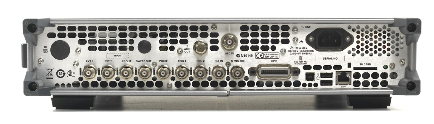
条件:Ext1 External AM/FM/PM #1 input: Nominal input impedance is 50 Ω/600 Ω/1MΩ
nominal: Damage levels are ± 5 V.
Ext2 External AM/FM/PM #2 input: Nominal input impedance is 50 Ω/600 Ω/1MΩ
nominal: Damage levels are ± 5 V.
logic levels are 0 V and high logic levels are +1 V. Nominal input impedance is 50
Trigger 1 (in) Accepts TTL and CMOS level signals for triggering point-to-point in sweep mode.
nominal. Input damage levels are ≤ –0.3 V and ≥ +5.3 V.
Reference input Accepts a 10 MHz reference signal used to frequency lock the internal time base.
Option 1ER adds the capability to lock to a frequency from 1 MHz to 50 MHz.
Nominal input level –3.5 to +20 dBm, impedance 50 Ω, sine or square waveform.
+5 dBm. Nominal output impedance 50 Ω. Input damage level is +16 dBm.
ALC in This female BNC connector is used for negative external detector leveling.
• Input impedance: 100 kΩ (nominal)
Front Panel Connectors (all connectors are BNC unless otherwise stated)
Z-Axis output This female BNC connector supplies a +5 V (nominal) level during retrace and
connector supplies a –5 V (nominal) level when the RF frequency is at a marker
frequency and intensity marker mode is on. The load impedance should be ≥ 5 kΩ.
Sweep out Generates output voltage
0 to +10 V when the signal generator is sweeping. This
output can also be programmed to indicate when the source is settled or output
pulse video and is TTL and CMOS compatible in this mode. Output impedance <
1
Ω, can drive 2 kΩ. Damage levels are
± 15 V.
Pulse External pulse modulation input. This input is TTL and CMOS compatible. Low
Ω. Input damage levels are ≤ –0.3 V and ≥
+5.3 V.
Damage levels are ≤ –0.3 V and ≥
+5.3 V.
Trigger 2 (out) Default use is with sweep mode. The signal is high at start of dwell, or when
waiting for point trigger in manual sweep mode; low when dwell is over or point
trigger is received. This output can also be programmed to indicate when the
source is settled, pulse synchronization, or pulse video. Outputs a 2.5V into
50 Ω
10 MHz out Outputs the
10 MHz reference signal used by internal time base. Level nominally
• Signal levels
-0.2 mV to -0.5 V
• Damage levels: < –12 V and >
1 V
band switch intervals of a step or list sweep. During step or list sweep, this
USB Type-A There are two USB
2.0 Type-A connectors on the rear panel. Used with a memory
stick for transferring instrument states, licenses and other files into or out of the
instrument; also used with U2000 Series USB power sensors.
USB Type-B There are one USB 2.0 Type-B connectors on the rear panel. The USB connector
以上指标摘自厂家官方数据手册,完整定义、测试条件与保证值口径以手册为准。完整指标、测试条件与定义口径请见产品页「软件和手册 | 白皮书」栏目中的官方数据手册。
是德科技 | KEYSIGHT · onetest 仪器资源库


 客服








 粤公网安备44030902003758