是德科技 | KEYSIGHT
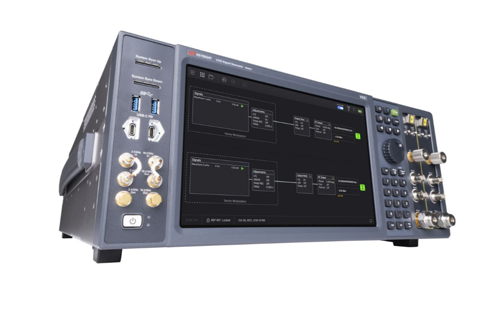
VXG系列M9384B 1MHz至14/20/31.8/44GHz双通道微波信号发生器 2GHz带宽 详细指标
矢量信号发生器
Temperature Operating 0 to 45 °C (single channel)
0 to 40 °C (dual channel)
Humidity Type tested at 95%, +40 °C (non-condensing) (From
40°C to 45°C
the maximum % relative humidity follows the line of constant dew
Type tested at 5 to 500 Hz
0.21 g rms
Survival random vibration
Type tested at 5 to 500 Hz
2.09 g rms
Functional shock Type tested at half-sine, 30 g
11 ms
Bench handling Type tested per MIL-PRF-28800F
Altitude Operating
3,000 m (Up to 10,000 feet approx.)
Storage
4,572 m (Up to 15,000 feet)
EMC Complies with European EMC Directive
条件:humidity, shock, vibration, altitude and power-line conditions. Test
– CISPR Pub 11 Group
1, class A
– ICES/NMB-001
This ISM device complies with Canadian ICES-001.
Cet appareil ISM est conforme a la norme NMB-001 du Canada.
Environmental testing Samples of this product have been type tested in accordance with
the Keysight Environmental Test Manual and verified to be robust
against the environmental stresses of storage, transportation and
end-use. Those stresses include but are not limited to temperature,
methods are aligned with IEC
60068-2 and levels are similar to
Weight Single channel (F14 or F20)
29 kg (63.2 lbs.)
Single channel (F32 or F44)
30 kg (66 lbs.)
Dual channel (F14 or F20)
32 kg (71.2 lbs.)
Dual channel (F32 or F44)
35 Kg (77.2 lbs.)
Dimensions (L x W x H) 578 mm x 450 mm x
190 mm (approx.)
Resolution 1280 x
768 pixels
Size
10.6 in (26.9 cm) diagonal
条件:Connectors Type Description 19.2 GHz Out 1 SMA female Output of 19.2 GHz CW frequency reference, cabled from the factory to 19.2 GHz In. This port is always-on level is 7.3 dBm (nominal), if alternate 19.2 GHz In is provided this port should be terminated with
interface; off by default. High impedance when off, 50 Ω when on, level is +15 dBm (nominal).
Internal Removable solid state drive (240 GB)
External Supports USB
3.0/2.0 compatible memory devices
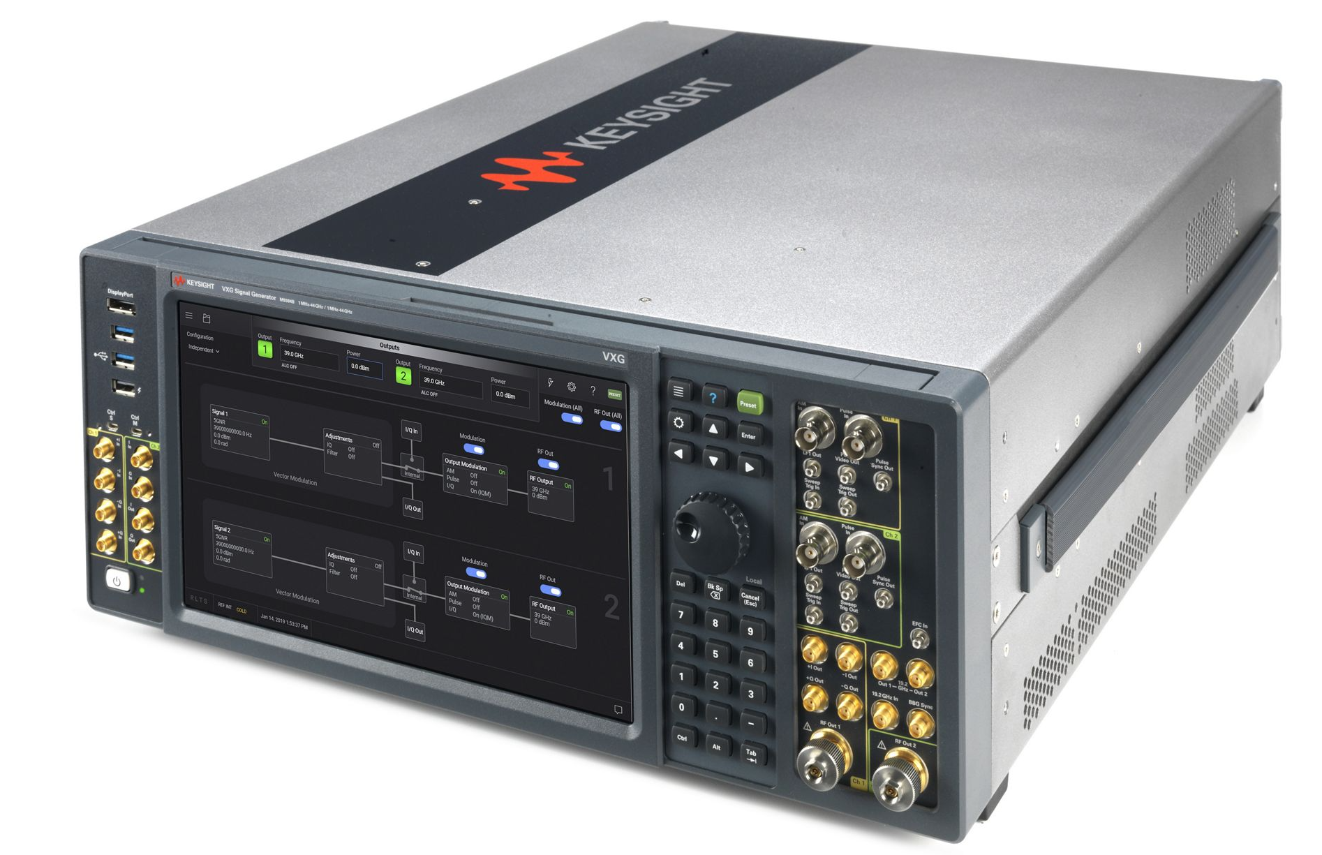
M9384B VXG Input and Output Connectors
M9384B front panel connectors
50 Ω load.
19.2 GHz Out
2 SMA female Output of 19.2 GHz CW frequency reference switched from user
interface; off by default. High impedance when off
50 Ω when on
level is
7.3 dBm (nominal).
100 MHz Out SMB male Output of 100 MHz CW frequency reference, switched from the user
Trig
1 SMB male For options F32/F44, reserved for future use.
For options F14/F20 with Options PME/PMR Pulse Video Out outputs
signal following envelope of RF pulse
条件:Instruments with Option 002 have connector for CH2.
3.3 V into high impedance. 50 Ω impedance (nominal). Damage level
is ± 5 V. Instruments with Option 002 have connector for CH2.
Instruments with Option 002 have connector for CH2.
AM In BNC female Reserved for future use. 50 Ω impedance (nominal). Damage level
is 10 V peak, 5 V rms. Instruments with Option 002 have connector
Pulse In BNC female For options PME/PMR externally provided Pulse modulation signal.
1 MΩ impedance (nominal). Damage level is 10 V peak, 5 V rms.
Instruments with Option 002 have connector for CH2.
into high impedance. 50 Ω impedance (nominal). Damage level is ±
5 V. Instruments with Option 002 have connector for CH2.
impedance. 50 Ω impedance (nominal). Damage level is ± 5 V.
Instruments with Option 002 have connector for CH2.
Trig
2 SMB male For options F32/F44, reserved for future use.
For options F14/F20 with Options PME/PMR Pulse Sync Out outputs
signal (trigger) related to pulse timing. VOL < 0.4 V, VOH is
2.8 V to
Settled SMB male Output signal to determine when the signal level is settled: logic
High while settled and low (approximately
0v) when change is in
progress. CMOS +3.3 V Logic. Damage level is < -5 V and >
6.5 V.
EFC In SMB male Reserved for future use. ESD damage level is
30 V.
LF1 Out SMB male Reserved for future use.
for CH2.
Pulse Video Out SMB male For options F32/F44 with Options PME/PMR, outputs signal
following envelope of RF pulse. VOL < 0.4 V, VOH is
2.8 V to 3.3 V
Pulse Sync Out SMB male For options F32/F44 with options PME/PMR, outputs signal (trigger)
related to pulse timing. VOL < 0.4 V, VOH is
2.8 V to 3.3 V into high
RF Out
1/2 Option F32/F44 – 2.4
条件:(nominal). Instruments with Option 002 have connector for CH2.
Option F14/F20 –
RF Output signal, level selected by user interface.
50 Ω impedance
M9384B front panel connectors (continued)
条件:(nominal). 50 Ω impedance (nominal). Damage level is ± 2 V.
CH2 I Out SMA female For instruments with Option 002, outputs the in-phase component of
MHz (nominal). 50 Ω impedance (nominal). Damage level is ± 2 V.
Frequency range is DC to 1000 MHz (nominal). 50 Ω impedance
(nominal). Damage level is ± 2 V.
1000 MHz (nominal). 50 Ω impedance (nominal). Damage level is ±
CH2 Q Out SMA female For instruments with Option 002, outputs the quadrature component
1000 MHz (nominal). 50 Ω impedance (nominal). Damage level is ±
Out. Frequency range is DC to 1000 MHz (nominal). 50 Ω
impedance (nominal). Damage level is ± 2 V.
CH1 I+ In SMA female For option EXT, externally supplied analog in-phase component of
Frequency range is DC to 1000 MHz (nominal). 50 Ω impedance
(nominal). Damage level is 5 V peak, 1 V rms.
CH2 I In SMA female For Option EXT and Option 002, input for in-phase component of
MHz (nominal). 50 Ω impedance (nominal). Damage level is 5 V
CH1 I- In SMA female For option EXT, externally supplied analog in-phase component of
of phase from I+ In. Frequency range is DC to 1000 MHz (nominal).
50 Ω impedance (nominal). Damage level is 5 V peak, 1 V rms.
CH1 Q+ In SMA female For Option EXT, externally supplied analog quadrature-phase
generator. Frequency range is DC to 1000 MHz (nominal). 50 Ω
impedance (nominal). Damage level is 5 V peak, 1 V rms.
CH2 Q In SMA female For option EXT and Option 002, input for quadrature component of
MHz (nominal). 50 Ω impedance (nominal). Damage level is 5 V
CH1 Q- In SMA female For Option EXT, externally supplied analog quadrature-phase
1000 MHz (nominal). 50 Ω impedance (nominal). Damage level is 5
operation. +5 dBm (nominal). 50 Ω impedance (nominal). Damage
CH1 +I Out SMA female Analog in-phase component of I/Q modulation from channel
1’s
internal baseband generator. Frequency range is DC to 1000 MHz
channel
2’s analog I/Q modulation. Frequency range is DC to 1000
CH1 -I Out SMA female Analog in-phase component of I/Q modulation from channel
1’s
internal baseband generator
180° out of phase from +I Out.
CH1 +Q Out SMA female Analog quadrature-phase component of I/Q modulation from
channel
1’s internal baseband generator. Frequency range is DC to
2 V.
of channel
2’s analog I/Q modulation. Frequency range is DC to
2 V.
CH1 -Q Out SMA female Analog quadrature-phase component of I/Q modulation from
channel 1’s internal baseband generator
180° out of phase from +Q
I/Q modulation to channel
1’s internal baseband generator.
channel
2’s analog I/Q modulation. Frequency range is DC to 1000
I/Q modulation to channel 1’s internal baseband generator
180° out
component of I/Q modulation to channel
1’s internal baseband
channel
2’s analog I/Q modulation. Frequency range is DC to 1000
component of I/Q modulation to channel
1’s internal baseband
generator 180° out of phase from Q+ In. Frequency range is DC to
19.2 GHz In SMA female Input for 19.2 GHz CW frequency reference required for instrument
M9384B front panel connectors (continued)
wired-or of the two channels
条件:Ctrl M uHDMI female Reserved for future use. Damage level is < -5 V and > 6.5 V.
Ctrl S uHDMI female Reserved for future use. Damage level is < -5 V and > 6.5 V.
USB 3.0 USB Type-A female Host controller, SuperSpeed, 900 mA (nominal)
USB 2.0 USB Type-A female Host controller, high-speed, 1.2 A (nominal)
Display Port DisplayPort For external display devices. Display port dual mode DisplayPort++
(DVI-D, VGA, HDMI with an adapter)
NOTE: To duplicate the instrument’s application on an external
display it is recommended to set the resolution to 1280x768.
功率 Green LED Indicates 功率开
条件:Power Yellow LED Indicates AC power is connected and some internal circuitry is live.
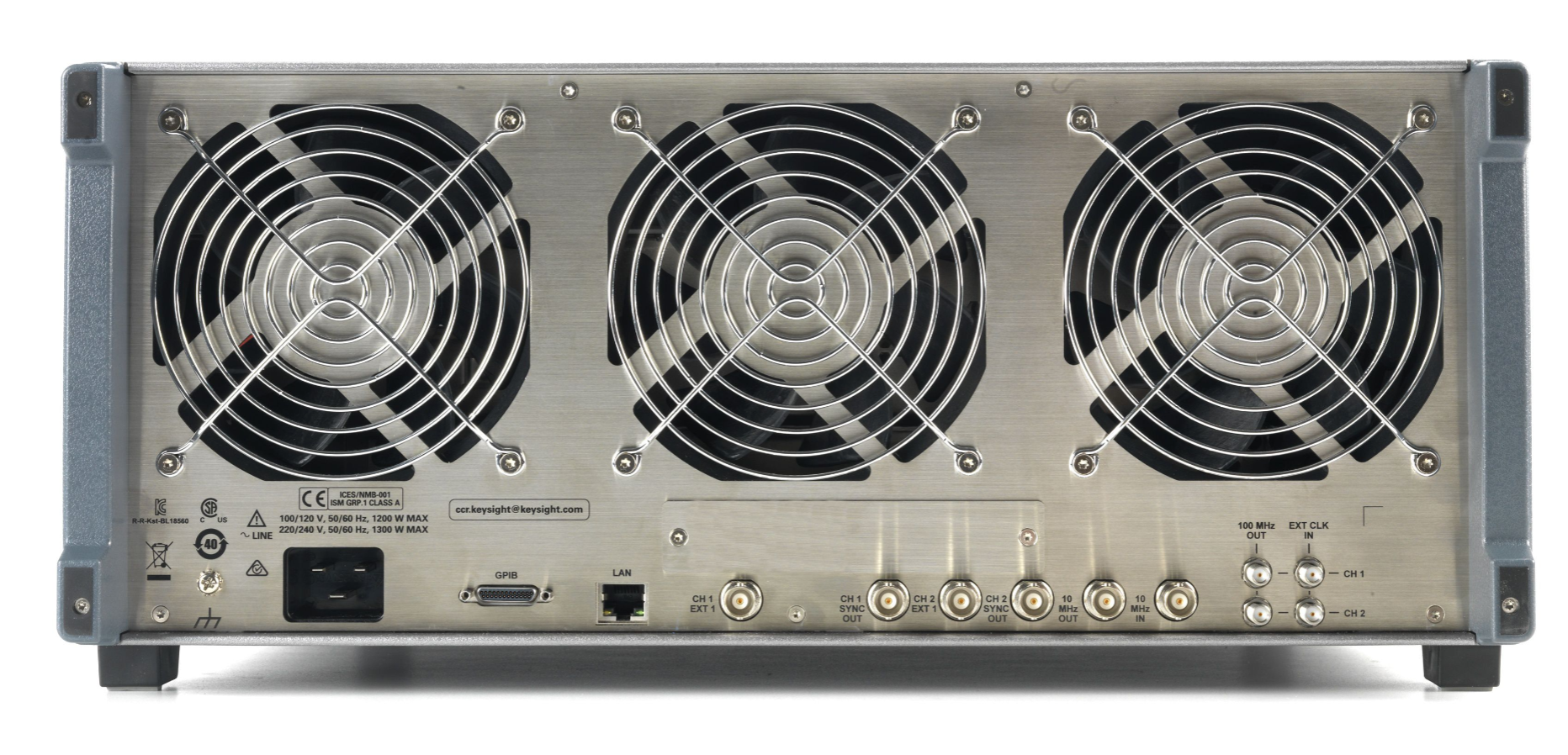
Connectors Type Description 10 MHz In BNC female Externally supplied 10 MHz CW frequency reference, switched by the user interface; off by default. Input level -3 dBm to +20 dBm (nominal), 50
dBm (nominal). 50 Ω impedance (nominal). ESD damage level is 30 V.
EXT CLK IN. This port is always-on level is +15 dBm (nominal). If
impedance (nominal). Damage level is ± 5 V.
impedance (nominal). Damage level is ± 5 V. Unused if Option 002 is not
M9384B rear panel connectors
Ω impedance. ESD damage level is
30 V.
10 MHz Out BNC female Output of 10 MHz CW frequency reference, this port is always on.
+15
100 MHz Out SMA female Output of 100 MHz CW frequency reference, cabled from the factory to
alternate EXT CLK IN is provided this port should be terminated with 50 Ω
load. Connector for CH1 and CH2.
CH1 EXT 1 BNC female External baseband generator trigger input for channel 1.
10 kΩ input
CH2 EXT 1 BNC female External baseband generator trigger input for channel 2.
10 kΩ input
条件:CH1 SYNC OUT BNC female Output of TTL High as assigned to Signal’s Marker Setup for channel 1.
(nominal). Damage level is ± 5 V.
CH2 SYNC OUT BNC female Output of TTL High as assigned to Signal’s Marker Setup for channel 2.
(nominal). Damage level is ± 5 V. Unused if Option 002 is not present.
operation. +10 dBm (nominal). 50 Ω impedance (nominal). Damage level
VOL < 0.4 V, VOH is 2.8 V to 3.3 V into high impedance.
50 Ω impedance
VOL < 0.4 V, VOH is 2.8 V to 3.3 V into high impedance.
50 Ω impedance
EXT CLK IN SMA female Input of an external
100 MHz reference clock required for instrument
is +20 dBm. One per channel, channel 2 is unused if option
002 is not
GPIB Micro-D 25-pin IEEE-488.2
1987 with listen and talk. Use accessory Y1260A for GPIB
LAN RJ45 Ethertwist GbE
10/100/1000BASE-T Ethernet: the LAN supports DHCP, connection
monitoring, dynamic hostname services, TCP/IP communication, TCP
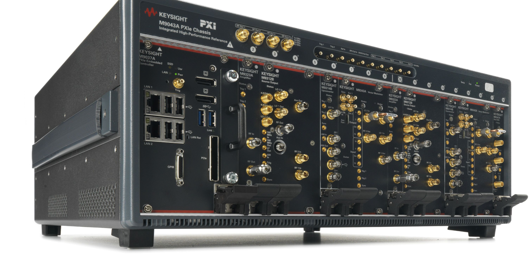
M9312B 3 PXIe slots 205 mm x 61.8 mm x 130 mm
1.9 kg (4.2 lbs.)
M9314B 1 PXIe slot 205 mm x 21.2 mm x 130 mm
0.6 kg (1.4 lbs.)
M9323A 1 PXIe slot 205 mm x 21.2 mm x 130 mm
0.6 kg (1.4 lbs.)
M9343A 3 PXIe slots 205 mm x 61.8 mm x 130 mm
1.6 kg (3.6 lbs.)
M9347A 1 PXIe slot 205 mm x 20.2 mm x 130 mm
0.7 kg (1.6 lbs.)
M9383B VXG-m Input and Output Connectors
M9312B input and output connectors
Connectors Type Description 4.8 GHz In APC female (3.5 mm) Inputs a 4.8 GHz reference clock from the M9043A Chassis
4.8
4.8 GHz Out APC female (3.5 mm) Outputs a copy of 4.8 GHz signal accepted by the
4.8 GHz In
LO 2 Out APC female (3.5 mm) Outputs either a copy of LO 1 In signal or a doubled copy of LO
1
In signal (selectable) to the M9314B LO
1 In connector.
100 MHz In SMP male Inputs a 100 MHz reference signal from the M9043A Chassis
100
100 MHz Out SMP male Outputs a copy of the 100 MHz reference signal (received by
100
MHz In connector) to the M9347A Ref In connector.
LF Out SMP male Outputs a waveform from the internal function generator or a copy
of the AM modulated signal
条件:AM In SMP male Reserved for future use. 0 to 1 MHz (nominal). 1.0 V (nominal) for
100% AM. 1 MΩ impedance (nominal). Damage level is ± 15 V.
Trig 1 SMP male Accepts a bi-directional trigger signal from the M9343A Ext
2
Trig 2 SMP male Accepts a bi-directional trigger signal from the M9314B Trig
2
Sync Out SMP male Accepts a bidirectional signal used for synchronization with other
LO 1 In SMA female Accepts an LO signal between
400 MHz and 10 GHz from the
M9347A Synth
1 Out connector.
LO 1 Out SMA female Outputs either a copy of LO 1 In signal or a doubled copy of LO
1
In signal (selectable) to the M9343A LO
1 In connector.
RF Out Female (2.4 mm) Outputs an RF signal between
1 MHz and 20 GHz to the M9323A
RF In connector when Aux Out is connected to Aux In. Otherwise,
outputs the signal to the Aux Out connector attenuated by the
条件:Aux Out SMA female Provides an output signal to the M9314B Aux In connector.
Aux In SMA female Accepts an input signal between
1 MHz to 44 GHz from the
M9314B Aux Out connector.
RF 2 In SMA female Inputs an IF signal between
400 MHz and 3.2 GHz from the
M9343A RF
2 Out connector.
RF 1 In SMA female Inputs an IF signal between
3.2 GHz and 20 GHz from the
M9314B RF
1 Out connector.
M9314B input and output connectors
条件:signal. 1 MΩ impedance (nominal). Damage level is 10 V peak, 5
Trig 1 SMP male For options PME/PMR externally provided pulse modulation
条件:Trig 2 SMP male Outputs the trigger signal to the M9312B Trig 2 connector.
Sync SMP male Accepts a bidirectional signal used for synchronization with other
条件:AM Out SMP male Reserved for future use. 50 Ω impedance (nominal). Damage
AM In SMP male Accepts an external amplitude modulated signal with 50%/volt or
20 dB/volt (selectable).
level is 10 V peak
5 V rms.
LO 1 In Female (2.4 mm) Inputs an LO signal between
22 GHz and 38 GHz from the
M9312B LO
2 Out connector.
RF 1 Out SMA female Outputs a copy of the RF 1 In signal to the M9312B RF
1 In
RF 1 In SMA female Inputs the IF signal between
400 MHz and 20 GHz from the
M9343A RF
1 Out connector.
Aux In SMA female Accepts an input signal between
1 MHz and 20 GHz from the
M9312B Aux Out connector.
Aux Out Female (2.4 mm) Provides a RF output as either the upconverted signal from RF
1
In connector or the Aux In signal to the M9312B Aux In connector.
M9323A input and output connectors
Trig 1 SMP male For Options F32/F44 with Options PME/PMR, outputs signal following envelope
of RF pulse. VOL < 0.4 V, VOH is 2.8 V to 3.3 V into high impedance.
50 Ω
Trig 2 SMP male For Options F32/F44 with Options PME/PMR, outputs signal (trigger) related to
pulse timing. VOL < 0.4 V, VOH is 2.8 V to 3.3 V into high impedance.
50 Ω
条件:Sync SMP male Accepts a bidirectional signal used for synchronization with other modules.
RF 1 Out Female (2.4 mm) RF Output signal, level selected by user interface. 50 Ω impedance (nominal).
RF 1 In Female (2.4 mm) Accepts a RF signal from the M9312B RF Out connector.
M9343A input and output connectors
Sync SMB male Intended for future use
条件:Ext 1 SMB male External trigger input. 10 kΩ input impedance (nominal).
Ext 2 SMB male Outputs the trigger signal to the M9312B Trig 1 connector.
Ext Clk In SMB male Inputs a 100 MHz signal from the M9043A Chassis 100 MHz Out 4 connector.
Aux Port Reserved for future use
条件:I+ Input SMP male For option EXT, externally supplied analog in-phase component of I/Q
MHz (nominal). 50 Ω impedance (nominal). Damage level is 5 V peak, 1 V rms.
I- Input SMP male For option EXT, externally supplied analog in-phase component of I/Q
modulation to internal baseband generator, 180° out of phase from I+ In.
Frequency range is DC to 1000 MHz (nominal). 50 Ω impedance (nominal).
Q+ Input SMP male For option EXT, externally supplied analog quadrature-phase component of I/Q
MHz (nominal). 50 Ω impedance (nominal). Damage level is 5 V peak, 1 V rms.
Q- Input SMP male For option EXT, externally supplied analog quadrature-phase component of I/Q
modulation to internal baseband generator, 180° out of phase from Q+ In.
Frequency range is DC to 1000 MHz (nominal). 50 Ω impedance (nominal).
generator. Frequency range is DC to 1000 MHz (nominal). 50 Ω impedance
(nominal). Damage level is ± 2 V.
180° out of phase from +I Out. Frequency range is DC to 1000 MHz (nominal).
50 Ω impedance (nominal). Damage level is ± 2 V.
generator. Frequency range is DC to 1000 MHz (nominal).
50 Ω impedance (nominal). Damage level is ± 2 V.
USB Port Reserved for future use. Not for use with USB devices.
modulation to internal baseband generator. Frequency range is DC to 1000
Damage level is 5 V peak
1 V rms."
modulation to internal baseband generator. Frequency range is DC to 1000
Damage level is 5 V peak
1 V rms.
I+ Output SMP male Analog in-phase component of I/Q modulation from internal baseband
I- Output SMP male Analog in-phase component of I/Q modulation from internal baseband generator,
Q+ Output SMP male Analog quadrature-phase component of I/Q modulation from internal baseband
Q- Output SMP male Analog quadrature-phase component of I/Q modulation from int
以上指标摘自厂家官方数据手册,完整定义、测试条件与保证值口径以手册为准。完整指标、测试条件与定义口径请见产品页「软件和手册 | 白皮书」栏目中的官方数据手册。
是德科技 | KEYSIGHT · onetest 仪器资源库


 客服










 粤公网安备44030902003758