是德科技 | KEYSIGHT
S9115A 49.2GHz 收发信机 1.2GHz 详细指标
Wideband RF transceiver testing
• The characteristics provided in this data sheet for operation at or below
13 GHz are a subset of the
specifications for the Keysight M9415A PXIe VXT Vector Transceiver module. For the most recent
detailed performance information, refer to the M9415A Data Sheet (literature no.
3120-1518EN). Note
that the performance characteristics in that data sheet apply at the input/output connectors of the
M9415A module, but in the S9115A system, there is approximately
0.25 to 0.5 dB of insertion loss
between the S9115A front panel connectors and the M9415A due to the M9155C switch module and
• The Sub
13 GHz amplitude characteristics in this data sheet include the effects of the added system
• The M9415A-001 in this S9115A
5G Multi-Band Vector Transceiver is configured with: Option F12
(Frequency Range
380 MHz to 13 GHz), Option B12 (1.2 GHz BW), Option M05 (512 MSa memory)
Option
1EA (High Output Power).
条件:temperature ranges 20 to 35 °C, unless otherwise noted.
Nominal (nom) Describes the expected mean or average performance, or an attribute whose performance is
by design, such as the 50 Ω connector. This data is measured at room temperature
(approximately 25 °C). Nominal performance is not warranted.
expected performance, such as amplitude drift vs. time. This data is measured at room
temperature (approximately 25 °C). Measured performance is not warranted.
Specifications Describes the performance of parameters covered by the product warranty and apply to
Typical (typ) Describes additional product performance information that is not covered by the product
warranty. It is performance beyond specifications that 95% of the units exhibit with a
95%
confidence level at room temperature (approximately
25 °C). Typical performance does not
include measurement uncertainty. Typical performance is not warranted.
Measured (meas) Describes an attribute measured during the design phase for purposes of communicating
Recommended best practices
条件:seven standard configurations with multiple input and output connectors.
Each standard configuration allows you to select frequency range options, shown as below:
• Set chassis fan to high at environmental temperatures above
45 °C.
S9115A Standard Configurations
This data sheet contains system performance for the S9115A base system that is available in the following
• S9115A-TR1/TN1 5G Multi-Band Vector Transceiver, one RF and mmWave transceiver channel
• S9115A-TR2/TN2 5G Multi-Band Vector Transceiver, two RF and mmWave transceiver channel
• S9115A-BK1: TR1 with blocker signal capability
• S9115A-RF1
5G Multi-Band Vector Transceiver, one RF only (no mmWave) transceiver channel
• S9115A-RF2
5G Multi-Band Vector Transceiver, two RF only (no mmWave) transceiver channel
RF Transceiver Frequency Range mmWave Transceiver Frequency Range
适用型号选件 F08 选件 F13 选件 F43 选件 F49
条件:Each S9115A standard configuration has a different set of output and input connectors (ports):
Please refer to Table 1, and Figures 1, 2 for locations of the referenced connections.
380 MHz – 8 GHz 380 MHz – 13 GHz 22.7 – 43.5 GHz
22.7 – 49.2 GHz
S9115A-TR1/TN1 √ √ √ √
S9115A-TR2/TN2 √ √ √ √
S9115A-BK1 √ √ √ √
S9115A-RF1 √ √ n/a n/a
S9115A-RF2 √ √ n/a n/a
S9115A connectors (Ports
1 to 6)
RF Tx/Rx ① R F Tx/Rx ② RF Out ③ RF In ④ RF Tx/Rx ① RF Tx/Rx ② RF Out ⑤ RF In ⑥ Blocking TRX ⑦
S9115A-TR1/TN1 √ √ √ √
S 9115A-TR2/TN2 √ √ √ √ √ √ √ √
S9115A-RF1 √ √
S9115A-RF2 √ √ √ √
S9115A-BK1 √ √ √ √ √
Located on base system Located on M1749B RRH Located on base system
C onfiguration Located on M1749B RRH mmWave Transceiver RF Transceiver mmWave Transceiver RF Transceiver
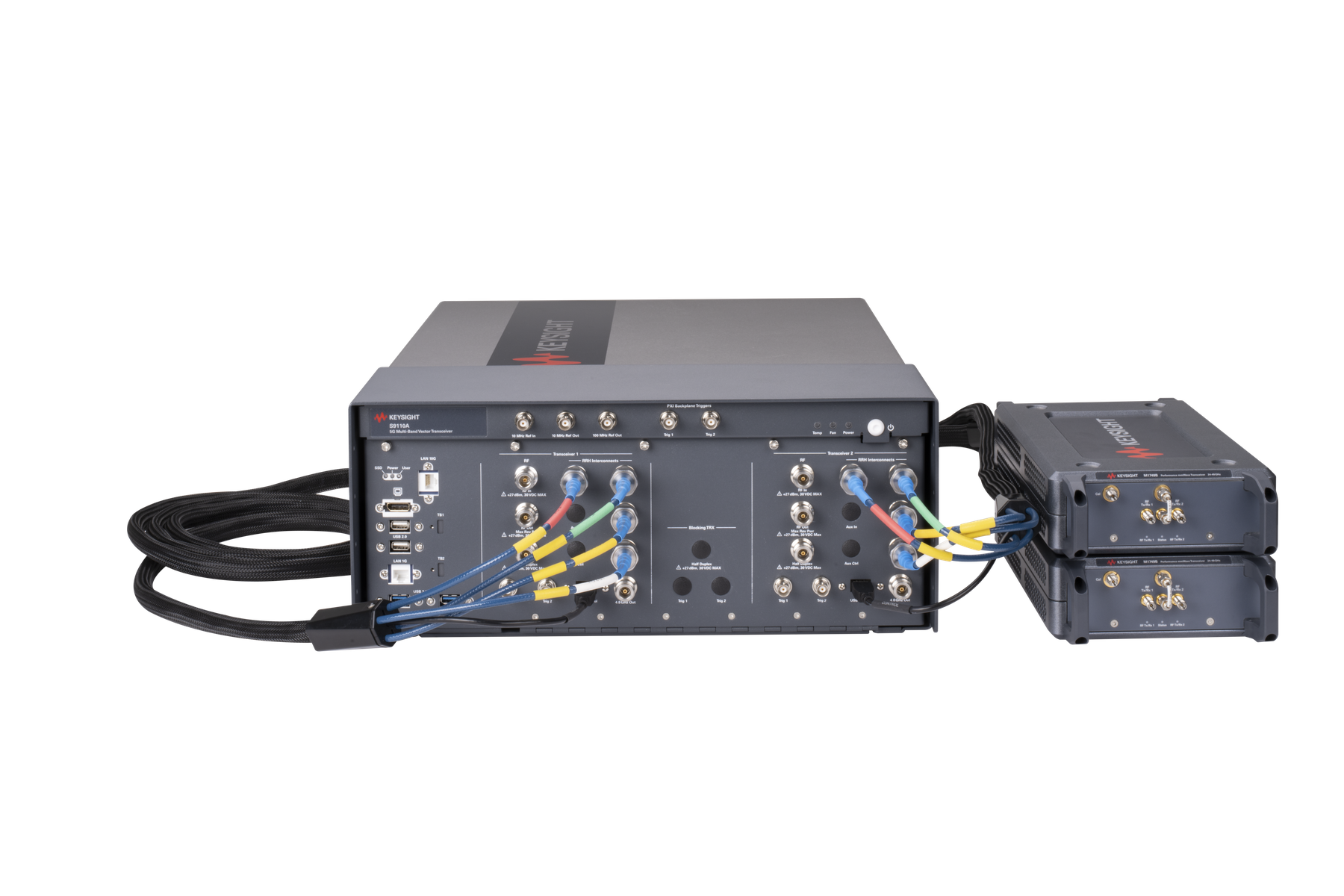
Figure 1. S9115A-TR1/TN1 (with F43 or F49 options)
5G Multi-Band Vector Transceiver configuration
Figure 2. S9115A-TR2/TN2 (with F43 or F49 options)
5G Multi-Band Vector Transceiver configuration
M1749B mmWave connectors (Option F49)
RF Tx/Rx 1 and RF Tx/Rx
2
22.7 to 43.5 GHz settable (F43)
22.7 to 49.2 GHz settable (F49)
All S9115A standard configurations RF
RF In or RF In
380 to 13000 MHz
条件:Center frequency Maximum bandwidth (nominal)
M1749B mmWave connectors (Option F49)
RF Tx/Rx 1 and RF Tx/Rx
2
All S9115A standard configurations RF
RF In or RF In 380 to 550 MHz 100 MHz 550 to 1310 MHz 200 MHz 1310 to 2000 MHz
600 MHz
2000 to 12400 MHz
1200 MHz
12400 MHz to 13000 MHz Bandwidth reduces as
13 GHz edge frequency is
M1749BmmWave connectors (Option F49)
RF Tx/Rx 1 and RF Tx/Rx
2
22.7 to 43.5 GHz (F43)
22.7 to 49.2 GHz (F49)
–70 dBm to +5 dBm
–70 dBm to +5 dBm
All S9115A standard configurations RF
RF In or RF In 380 to 13000 MHz
–150 dBm to +27 dBm
Half duplex connector (Option HD1, HD2) 380 to 13000 MHz
–150 dBm to +27 dBm
M1749B mmWave connectors (Option F49)
RF Tx/Rx 1 and RF Tx/Rx
2
Frequency range Level Accuracy 22.7 to 43.5 GHz –50 to 0 dBm ≤ ±2.10 dB, ±0.95 dB typical 43.5 to 49.2 GHz –50 to –5 dBm ≤ ±1.95 dB
±0.85 dB typical
All S9115A standard configurations RF
条件:Frequency range Level Accuracy (nominal) 380 to 1310 MHz –70 to +10 dBm ≤ ± 0.2 dB 1310 to 4300 MHz –70 to +10 dBm ≤ ± 0.3 dB 4300 to 8400 MHz –70 to +10 dBm ≤ ± 0.3 dB
Frequency range Level Accuracy (nominal) 380 to 1310 MHz –70 to +10 dBm ≤ ± 0.3 dB 1310 to 4300 MHz –70 to +10 dBm ≤ ± 0.3 dB 4300 to 8400 MHz –70 to +10 dBm ≤ ± 0.3 dB
Frequency range Input level Linearity (nominal) 22.7 - 43.5 GHz –50 to –20 dBm ≤ ± 1.0 dB
8400 to 11400 MHz –70 to +10 dBm ≤
± 0.4 dB
11400 to 12000 MHz –70 to +10 dBm ≤
± 0.4dB
12000 to 13000 MHz –70 to +10 dBm ≤
± 0.4 dB
Half duplex connector (Option HD1, HD2, HDB)
8400 to 11400 MHz –70 to +10 dBm ≤
± 0.3 dB
11400 to 12000 MHz –70 to +10 dBm ≤
± 0.4 dB
12000 to 13000 MHz
–70 to +10 dBm ≤ ±.0.4 dB
Linearity (CW mode) (reference power level is
-5 dBm)
M1749B mmWave connectors
RF Tx/Rx 1 and RF Tx/Rx
2
43.5 - 49.2 GHz –50 to –20 dBm ≤
± 1.0 dB
条件:Frequency range Input level Scale fidelity (nominal) 22.7 - 43.5 GHz –50 to –40 dBm ≤ ± 0.6 dB
M1749B mmWave connectors
RF Tx/Rx 1 and RF Tx/Rx
2
43.5 - 49.2 GHz –50 to –40 dBm ≤
± 0.6 dB
条件:Frequency range Bandwidth Flatness (nominal) 24.3 to 43.5 GHz 1200 MHz ± 1.25 dB 43.5 to 48.6 GHz 1200 MHz ± 1.25 dB
M1749B mmWave connectors
RF Tx/Rx 1 and RF Tx/Rx
2
All S9115A standard configurations RF
RF · 或 RF · 或 half duplex 连接器
条件:Frequency range Bandwidth Flatness (nominal) 380 to 550 MHz 100 MHz ± 0.80 dB
1310 to 1620 MHz
± 0.35 dB
1620 to 2000 MHz
± 0.35 dB
2000 to 3500 MHz
± 0.15 dB
3500 to 4300 MHz
± 0.20 dB
4300 to 12000 MHz
± 0.50 dB
12000 to 13000 MHz
± 0.50 dB
380 to 550 MHz
200 MHz
N/A 550 to 1310 MHz ± 0.40 dB 1310 to 1620 MHz ± 0.40 dB 1620 to 2000 MHz
± 0.40 dB
2000 to 3500 MHz
± 0.25 dB
3500 to 4300 MHz
± 0.25 dB
4300 to 12000 MHz
± 0.50 dB
12000 to 13000 MHz
± 0.50 dB
380 to 550 MHz
600 MHz
N/A 550 to 1310 MHz N/A 1310 to 1620 MHz ± 0.95 dB 1620 to 2000 MHz
± 0.30 dB
2000 to 3500 MHz
± 0.30 dB
3500 to 4300 MHz
± 0.40 dB
4300 to 12000 MHz
± 0.70 dB
12000 to 13000 MHz
± 0.50 dB
380 to 550 MHz
1200 MHz
N/A 550 to 1310 MHz N/A 1310 to 1620 MHz N/A
1620 to 2000 MHz N/A
2000 to 3500 MHz
± 0.35 dB
3500 to 4300 MHz
± 0.45 dB
4300 to 12000 MHz
± 0.80 dB
12000 to 13000 MHz
± 0.50 dB
条件:Frequency range 24.5 to 43.5 GHz EVM (nominal)
Frequency range 43.5 to 49.2 GHz EVM (nominal)
Test signal for FR1: 5G NR, 30 kHz subcarrier spacing
256QAM
Test signal for FR2: 5G NR, 120 kHz subcarrier spacing
256QAM
M1749B mmWave connectors
RF Tx/Rx 1 and RF Tx/Rx
2
100 MHz BW
≤ –37 dB
–40 to –30 dBm input power
≤ –43 dB
–30 to –5 dBm input power
≤ –43 dB
–5 to 0 dBm input power
400 MHz BW
≤ –32 dB
–40 to –25 dBm input power
≤ –42 dB
–25 to –5 dBm input power
≤ –40 dB
–5 to 0 dBm input power
8 x 100 MHz ≤ –30 dB
–40 to –25 dBm input power
≤ –42 dB
–25 to 0 dBm input power
100 MHz BW ≤ –37 dB
–40 to –30 dBm input power
≤ –43 dB
–30 to –5 dBm input power
400 MHz BW ≤ –32 dB
–40 to –25 dBm input power
≤ –42 dB
–25 to –5 dBm input power
8 x 100 MHz ≤ –30 dB
–40 to –25 dBm input power
≤ –42 dB
–25 to –5 dBm input power
All S9115A standard configurations RF
FR1 (Sub
13 GHz) EVM (nominal)
100 MHz BW signal at 5000 MHz
< 0.3% at –10 dBm input power
Adjacent channel leakage ration (ACLR)
条件:Frequency range 22.7 to 43.5 GHz ACLR (nominal)
Frequency range 43.5 to 49.2 GHz ACLR (nominal)
M1749B mmWave connectors
RF Tx/Rx 1 and RF Tx/Rx
2
100 MHz BW
≤ –47 dBc
–40 to –30 dBm input power
≤ –50 dBc
–30 to –10 dBm input power
≤ –48 dBc
–10 to 0 dBm input power
400 MHz BW
≤ –41 dBc
–40 to –30 dBm input power
≤ –44 dBc
–30 to –5 dBm input power
≤ –43 dBc
–5 to 0 dBm input power
≤ –37 dBc
–40 to -30 dBm input power
≤ –42 dBc
–30 to –5 dBm input power
≤ –38 dBc
–5 to 0 dBm input power
100 MHz BW
≤ –47 dBc
–40 to –30 dBm input power
≤ –50 dBc
–30 to –10 dBm input power
≤ –43 dBc
–10 to 0 dBm input power
400 MHz BW
≤ –41 dBc
–40 to –30 dBm input power
≤ –44 dBc
–30 to –5 dBm input power
≤ –43 dBc
–5 to 0 dBm input power
8 x 100 MHz ≤ –37 dBc
–40 to –30 dBm input power
≤ –42 dBc
–30 to –5 dBm input power
All S9115A standard configurations RF
条件:FR1 (Sub 13 GHz) ACLR (nominal)
100 MHz BW signal at 5000 MHz <
–63 dBc at 0 dBm input power
M1749B mmWave connectors (Option F49)
RF Tx/Rx 1 and RF Tx/Rx
2
22.7 to 43.5 GHz, settable (F43)
43.5 to 49.2 GHz, settable (F49)
All S9115A standard configurations RF
RF Out or RF Out
380 to 13000 MHz
条件:Center frequency Maximum bandwidth (nominal)
M1749B mmWave connectors (Option F49)
RF Tx/Rx 1 and RF Tx/Rx
2
All S9115A standard configurations RF
RF Out or RF Out 380 to 550 MHz 100 MHz 550 to 1310 MHz 200 MHz 1310 to 2000 MHz
600 MHz
2000 to 12400 MHz
1200 MHz
12400 MHz to 13000 MHz Bandwidth reduces as
13 GHz edge frequency is
M1749B mmWave connectors (Option F49)
RF Tx/Rx 1 and RF Tx/Rx
2
22.7 GHz - 43.5 GHz CW
–70 to +10 dBm
Modulated
–40 dBm to +5 dBm
22.7 GHz - 49.2 GHz CW
–70 to +10 dBm
Modulated
–40 dBm to +5 dBm
S9115A option TR1 or TR2 RF transceiver
RF Out 380 to 13000 MHz
–150 dBm to +27 dBm
Option HD1 (RFHD), HD2, HDB 380 to 13000 MHz
–150 dBm to +27 dBm
M1749B mmWave connectors (Option F49)
RF Tx/Rx 1 and RF Tx/Rx
2
Frequency range Level Accuracy 22.7 to 43.5 GHz –50 to 0 dBm ≤ ± 1.95 dB, ±0.90 dB typical 43.5 to 49.2 GHz –50 to –5 dBm ≤ ± 1.85 dB
±0.75 dB typical
S9115A option TR1 or TR2 RF transceiver
条件:Frequency range Level Accuracy (nominal) 380 to 550 MHz –50 to 0 dBm ≤ ± 0.4 dB 550 to 4300 MHz –50 to 0 dBm ≤ ± 0.4 dB 4300 to 6000 MHz –50 to 0 dBm ≤ ± 0.5 dB
Frequency range Level Accuracy (nominal) 380 to 550 MHz –50 to 0 dBm ≤ ± 0.3 dB 550 to 4300 MHz –50 to 0 dBm ≤ ± 0.4 dB 1310 to 4300 MHz –50 to 0 dBm ≤ ± 0.5 dB
Frequency range Input level Linearity (nominal) 22.7 – 43.5 GHz –50 to –30 dBm ≤ ± 1.5 dB
6000 to 7800 MHz –50 to 0 dBm ≤
± 0.5 dB
7800 to 10200 MHz –50 to 0 dBm ≤
± 0.5 dB
10200 to 12000 MHz –50 to 0 dBm ≤
± 0.4 dB
12000 to 13000 MHz –50 to 0 dBm ≤
± 1.3 dB
Half duplex connector (Option HD1, HD2, HDB)
4300 to 8400 MHz –50 to 0 dBm ≤
± 0.5 dB
7800 to 10200 MHz –50 to 0 dBm ≤
± 0.5 dB
10200 to 12000 MHz –50 to 0 dBm ≤
± 0.5 dB
12000 to 13000 MHz –50 to 0 dBm ≤
± 1.3 dB
Linearity (CW mode) (reference power level is
-5 dBm)
M1749B mmWave connectors (Option F49)
RF Tx/Rx 1 and RF Tx/Rx
2
43.5 – 49.2 GHz –50 to –30 dBm ≤
± 1.5 dB
条件:Frequency range Bandwidth Flatness (nominal)
M1749B mmWave connectors (Option F49)
RF Tx/Rx 1 and RF Tx/Rx
2
24.3 to 43.5 GHz 1200 MHz
± 1.5 dB
43.5 to 48.6 GHz 1200 MHz
± 1.5 dB
All S9115A standard configurations RF
RF Out or RF HD Out or half duplex connector 380 to 550 MHz
100 MHz
± 0.70 dB
1310 to 1620 MHz
± 0.55 dB
1620 to 2000 MHz
± 0.40 dB
2000 to 3500 MHz
± 0.40 dB
3500 to 4300 MHz
± 0.40 dB
4300 to 6000 MHz
± 0.40 dB
6000 to 9000 MHz
± 0.40 dB
9000 to 10200 MHz
± 0.40 dB
10200 to 12000 MHz
± 0.40 dB
12000 to 13000 MHz
± 0.70 dB
380 to 550 MHz
200 MHz
N/A 550 to 680 MHz ± 0.45 dB 680 to 730 MHz ± 1.05 dB 730 to 1310 MHz
± 0.45 dB
1310 to 1620 MHz
± 0.55 dB
1620 to 2000 MHz
± 0.45 dB
2000 to 3500 MHz
± 0.45 dB
3500 to 4300 MHz
± 0.45 dB
4300 to 6000 MHz
± 0.45 dB
6000 to 9000 MHz
± 0.45 dB
9000 to 10200 MHz
± 0.45 dB
10200 to 12000 MHz
± 0.45 dB
12000 to 13000 MHz
± 0.70 dB
380 to 550 MHz
600 MHz
N/A 550 to 680 MHz N/A 680 to 730 MHz N/A
730 to 1310 MHz N/A
1310 to 1620 MHz
± 0.70 dB
1620 to 2000 MHz
± 0.50 dB
2000 to 3500 MHz
± 0.50 dB
3500 to 4300 MHz
± 1.00 dB
4300 to 6000 MHz
± 0.55 dB
6000 to 9000 MHz
± 0.55 dB
9000 to 10200 MHz
± 0.60 dB
10200 to 12000 MHz
± 0.65 dB
12000 to 13000 MHz
± 0.70 dB
380 to 550 MHz
1200 MHz
N/A 550 to 680 MHz N/A 680 to 730 MHz N/A
730 to 1310 MHz N/A
1310 to 1620 MHz N/A
1620 to 2000 MHz N/A
2000 to 3500 MHz
± 0.60 dB
3500 to 4300 MHz
± 1.00 dB
4300 to 6000 MHz
± 0.75 dB
6000 to 9000 MHz
± 0.55 dB
9000 to 10200 MHz
± 1.10 dB
10200 to 12000 MHz
± 0.65 dB
12000 to 13000 MHz
± 0.70 dB
条件:Frequency range 22.7 to 43.5 GHz EVM (nominal)
Frequency range 43.5 to 49.2 GHz EVM (nominal)
Test signal for FR1: 5G NR, 30 kHz subcarrier spacing
256QAM
Test signal for FR2: 5G NR, 120 kHz subcarrier spacing
256QAM
M1749B mmWave connectors (Option F49)
RF Tx/Rx 1 and RF Tx/Rx
2
100 MHz BW ≤ –33 dB
–40 to –30 dBm input power
≤ –42 dB
–30 to 0 dBm input power
400 MHz BW
≤ –28 dB
–40 to –30 dBm input power
≤ –37 dB
–30 to –25 dBm input power
≤ –41 dB
–25 to 0 dBm input power
800x 100 MHz BW ≤ –30 dB
–35 to –25 dBm input power
≤ –38 dB
–25 to –5 dBm input power
100 MHz BW ≤ –33 dB
–40 to –30 dBm input power
≤ –42 dB
–30 to 0 dBm input power
400 MHz BW
≤ –28 dB
–40 to –30 dBm input power
≤ –37 dB
–30 to –25 dBm input power
≤ –41 dB
–25 to 0 dBm input power
8 x 100 MHz ≤ –30 dB
–35 to –25 dBm input power
≤ –38 dB
–25 to –5 dBm input power
All S9115A standard configurations RF
FR1 (Sub
13 GHz) EVM (nominal)
100 MHz BW signal at 5000 MHz <
0.6% at –10 dBm output power
Adjacent channel leakage ration (ACLR)
条件:Frequency range 22.7 to 43.5 GHz ACLR (nominal)
Frequency range 22.7 to 49.2 GHz ACLR (nominal)
Test signal for FR1: 5G NR, 30 kHz subcarrier spacing
256QAM
Test signal for FR2: 5G NR, 120 kHz subcarrier spacing
256QAM
M1749B mmWave connectors (Option F49)
RF Tx/Rx 1 and RF Tx/Rx
2
100 MHz BW
≤ –47 dBc
–40 to –25 dBm input power
≤ –50 dBc
–25 to –5 dBm input power
≤ –48 dBc
–5 to 0 dBm input power
400 MHz BW
≤ –43 dBc
–30 to 0 dBm input power
≤ –42 dBc
–35 to –30 dBm input power
≤ –40 dBc
–40 to –35 dBm input power
8 x 100 MHz ≤ –36 dBc
–40 to –30 dBm input power
≤ –37 dBc
–30 to 0 dBm input power
100 MHz BW ≤ –47 dBc
–40 to –25 dBm input power
≤ –50 dBc
–25 to –5 dBm input power
400 MHz BW
≤ –40 dBc
–30 to –5 dBm input power
≤ –42 dBc
–35 to –30 dBm input power
≤ –43 dBc
–40 to –35 dBm input power
8 x 100 MHz ≤ –36 dBc
–30 to –5 dBm input power
≤ –37 dBc
–40 to –30 dBm input power
All S9115A standard configurations RF
条件:FR1 (Sub 13 GHz) ACLR (nominal)
100 MHz BW signal at 4000 MHz <
–57 dBc at 0 dBm input power
100 MHz BW signal at 5000 MHz <
–55 dBc at 0 dBm input power
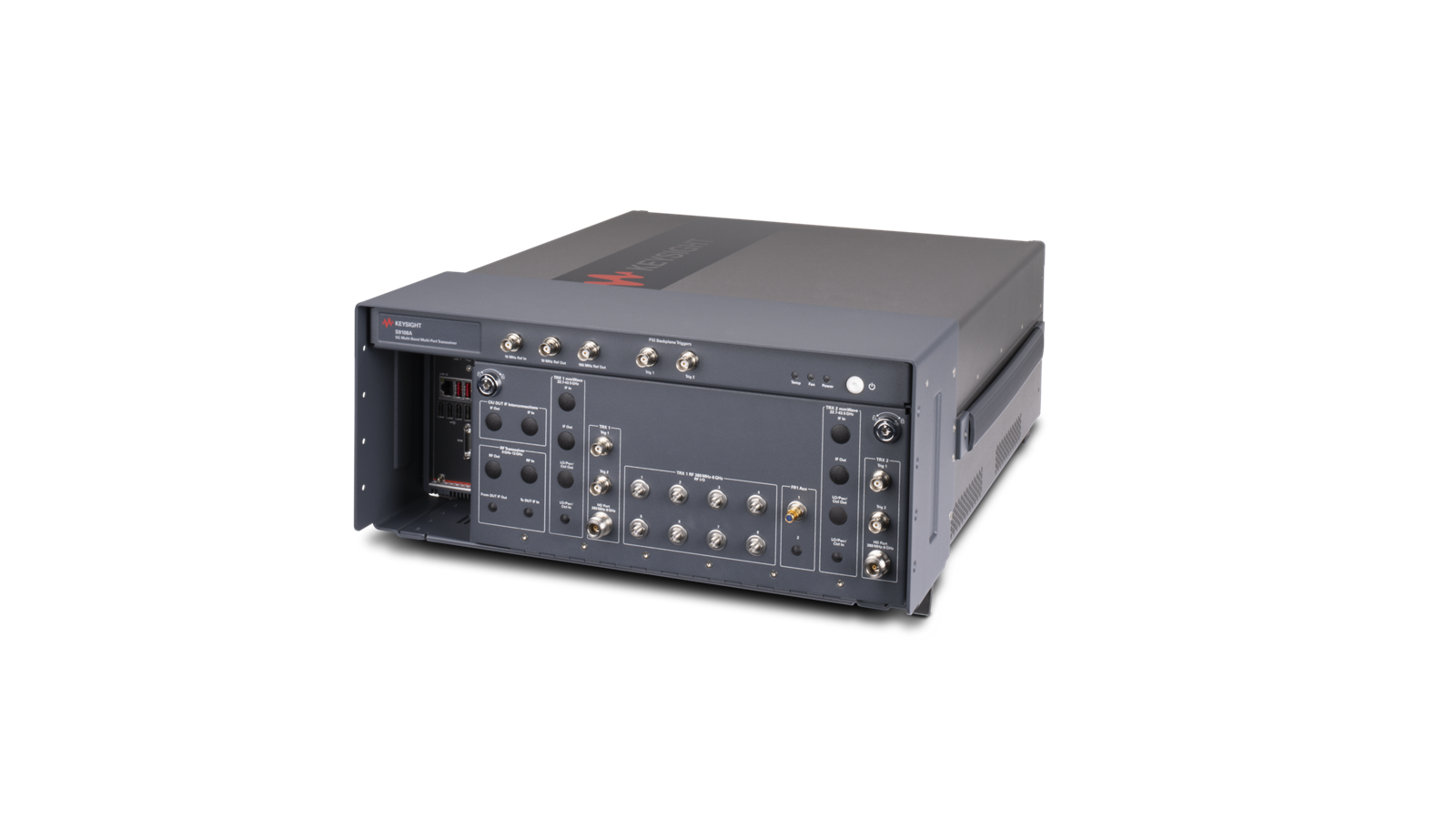
S9115A
5G multiband vector transceiver
Altitude up to 6,561.68 ft (2,000 m)
Operating temperature 15 to 35° C maximum relative humidity (non-condensing)
85% RH
S9115A base system (PXIe chassis with
modules, rugged panel, and cables) 100/120 V, 50/60 Hz 220/240 V, 50/60 Hz
1200 W Max (lower range)
1300 W Max (upper range)
M1749B 120 VAC (via supplied 0950-6166 AC/DC adapter)
105 W
S9115A base system
Height
197.8 mm (7.79 in); with feet installed
Width
449.5 mm (17.70 in); with rugged panel
Depth 568.9 mm (22.40 in); with rugged panel (from back bumper to front BNC)
S9101A rack space 2 X 2U x
1 rack width
S9115A-TR1/TN1 base system
20.4 kg (45.0 lbs)
S9115A-TR2/TN2 base system
22.6 kg (49.8 lbs)
S9115A-BK1 base system
24.0 kg (53.0 lbs)
S9115A-RF1 base system
20.9 kg (46.0 lbs)
S9115A-RF2 base system
22.7 kg (50.0 lbs)
Interface LAN RJ-45
条件:The recommended calibration cycle is one year; calibration services are available through Keysight service centers.
LAN, display port, and USB connectors, M9038A PXIe
LAN
1 and LAN2 (TCP/IP interface)
Connectors (Ethernet) One
10/100/1000 BASE-T (RJ-45)
One
100/1000/10GB BASE-T (RJ-45)
Connectors Two, USB
2.0 (Type A)
Connectors Two, USB
3.0 (Type A)
S9115A Base System Front Panel (with Rugged
条件:Accuracy ±16 Hz, typical, within 1 year since last calibration, from 20 to 30 °C.
Frequency reference
100 MHz Ref Out and 10 MHz Ref In/Out connectors above the rugged front panel
100 MHz Ref Out, frequency reference (if available)
Refer to the Keysight M9300A PXIe Frequency Reference Data Sheet for details on
Recommended calibration cycle
1 year
条件:Accuracy ± 1.6 Hz, typical, within 1 year since last calibration, from 20 to 30°C.
Amplitude
9.5 dBm (nominal)
10 MHz Ref Out, frequency reference
Refer to the Keysight M9300A PXIe Frequency Reference Data Sheet for details on
Recommended calibration cycle
1 year
条件:Connects behind rugged panel to M9300A PXIe reference Ref In and locks to another reference with a value from 1 to 110 MHz.
Amplitude
9.5 dBm (nominal)
10 MHz Ref In
条件:Input amplitude 0 to 10 dBm (nominal)
front panel connect to the PXI [0:7] backplane trigger bus in the M9019A chassis and can be configured as Input or Output.
Frequency
1 MHz to 110 MHz, sine wave
Lock range
± 1 ppm (nominal)
Trig 1 and Trig
2 connectors above the rugged front panel
Connects behind rugged panel to M9019A PXIe Chassis Trig 1 and Trig 2. These two front panel trigger connectors (Trig 1 and Trig
2) above the rugged
Direction control Input or output (configurable)
Output level 3.3 V CMOS (TTL compatible
5 V tolerant)
Output impedance
50 Ω (typical)
Output trigger source PXI_Trig0 - PXI_Trig7 (Segment
2 or 3)
Input level 3.3 V CMOS (TTL compatible
5 V tolerant)
Input impedance
3 kΩ (typical)
Input trigger destination PXI_Trig0 - PXI_Trig7 (Segment
2 or 3)
Input threshold
1.65 V (typical)
Minimum swing
250 mV (typical)
Minimum pulse width
100 ns (typical)
Transceiver connectors, RF
380 MHz to 13 GHz on the rugged front panel
条件:Connector Type-N (f), 50 Ω (nominal)
Frequency range
380 MHz to 6 GHz
Amplitude 0 VDC
+27 dBm maximum safe input power
条件:Connector Type-N (f), 50 Ω (nominal)
Connector Type-N (f), 50 Ω (nominal)
Frequency range
380 MHz to 6 GHz
Amplitude 0 VDC
+30 dBm maximum applied reverse input power
Half duplex, Option HD1, HD2
Frequency range
380 MHz to 6 GHz
Amplitude 0 VDC
+30 dBm maximum safe input power
条件:Input impedance 1 kΩ or 50 Ω nominal
Input level Range
0 to +3.3v
Output impedance
50 Ω nominal
Output Level
+3.3V LVTTL, LVDS
Transceiver connectors, head mmWave
22.7 to 49.2 GHz on the rugged front panel
IF In, IF Out, and LO/Pwr/Ctrl Out connect to the M1749B.
条件:Connector Type-N (f), 50 Ω (nominal)
Frequency range
380 MHz to 6 GHz
Amplitude ± 10 VDC
+33 dBm maximum
条件:Connector Type-N (f), 50 Ω (nominal)
Connector Type-N (f), 50 Ω (nominal)
Frequency range
380 MHz to 6 GHz
Amplitude ± 10 VDC
+33 dBm maximum
LO1 and LO2 Out
Frequency range
380 MHz to 6 GHz
条件:Connector Type-N (f), 50 Ω (nominal)
Connector USB
2.0 (Type A)
4.8 GHz Out (not used with F43/F49 options)
M1749B mmWave Transceiver
Although the M1749B mmWave transceiver is operational from 22.7 to 49.2 GHz, the performance information for the S9115A is only provided for the
frequency bands called out in this Data Sheet
条件:Connector 2.4 mm (f), 50 Ω (nominal)
These ports can be configured either to supply a mmWave signal to a Device Under Test (DUT) or to receive a
Amplitude 10 VDC
+10 dBm maximum input
9.6 GHz In
9.6 GHz Out
Control (not used with S9115A)
Connector
19 V DC power supply input
Keysight enables innovators to push the boundaries of engineering by quickly solving
design, emulation, and test challenges to create the best product experiences. Start your
This information is subject to change without notice. © Keysight Technologies, 202
3 - 2025
Published in USA, May 19 , 202 5 , 3123
-1356 .EN
条件:For more detailed product and specification information refer to the following literature and web pages:
Keysight M9019A PXIe 18 slot Chassis, Data Sheet (literature no.
5992-1481EN)
Keysight M9038A PXIe High Performance Embedded Controller, Data Sheet (literature no.
3122-1717.EN)
Keysight M9410A and M9411A PXIe VXT Vector Transceivers, Data Sheet (literature no.
5992-3331EN)
Keysight M9415A and M9416A PXIe VXT Vector Transceivers, Data Sheet (literature no.
3120-1518EN)
以上指标摘自厂家官方数据手册,完整定义、测试条件与保证值口径以手册为准。完整指标、测试条件与定义口径请见产品页「软件和手册 | 白皮书」栏目中的官方数据手册。
是德科技 | KEYSIGHT · onetest 仪器资源库


 客服










 粤公网安备44030902003758